
Full Product Manual


9Section 2 — ASSembly & Set-Up
Installing the Plenum (If necessary)
Note: Be careful not to damage the headlight
harness when installing the plenum.
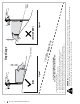
To install the plenum (a) onto the hood (b), first
insert the rear tabs (c) as shown in Figure 2-11.
(b)
(a)
(c)
Figure 2-11
With the rear tabs installed, insert the front tabs (a)
on the plenum (b) as shown in Figure 2-12.
(a)
(a)
(b)
(a)
Figure 2-12
Note: The rear tabs fit into a recessed area on the
top of the hood. They slide up from under the
hood and into these recessed areas.
Push up on the bottom of the plenum to make
sure that the plenum is securely in place.
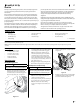
Secure the headlight harness (a) into the two
guides (b) on the front of the plenum. See
(b)
(a)
(b)
Figure 2-13
Installing the Dash Cap (If necessary)
To install the dash cap (a), line up the tabs (b) on
the dash cap (a) with the holes in the upper dash
as shown in Figure 2-14. Slide the tabs (b) into the
holes in the upper dash and push forward (c) on
the dash cap (a) to lock into place.
(a)
(b)(b)
(b)(b)
(a)
Figure 2-14
Note: Be sure to press on the lower part
of the dash cap (a) facing the operator
position to ensure the lower tabs on the
dash cap are in place.
Installing the Steering Wheel (If necessary)
The hardware for attaching the steering wheel has
been packed within the steering wheel, beneath
the steering wheel cap. Carefully pry off the
steering wheel cap and remove the hardware.
IMPORTANT! Do not use impact tools to install or
remove the steering wheel. Doing so may cause
damage to critical power steering components (if
so equipped).
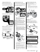
1. With the wheels of the tractor pointing
straight forward, align the steering wheel (a)
by using the center-line (b) on the front of the
steering wheel (a) pointing straight ahead
and the flat section (c) of the steering
wheel (a) facing toward the seat, place the
steering wheel (a) over the steering shaft (d).
See Figure 2-15.
(e)
(f)
(c)
(a)
(b)
(d)
Figure 2-15
2. Secure the steering wheel (a) with the hex bolt
(e) from under the steering wheel cap (f) and
torque to 18-22 ft.-lbs.
3. Place the steering wheel cap (f) over the
center of the steering wheel (a) and push
downward until it “clicks” into place.
Note: The hex bolt (e) securing the steering
wheel (a) has thread locker applied to it,
so if it is removed, it is recommended that
the hex bolt (a) be replaced or thread lock
re-applied.
Installing the Front Bumper (If necessary)
The hardware for attaching the front bumper is
shipped installed into the bumper.
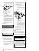
1. Remove the four hex screws (a) from the
bumper (b).
2. Position the bumper brackets to the inside of
the tractor’s frame and secure it in place with
the four hex flange screws (a). See Figure 2-16.
(a) (a)
(b)
Figure 2-16
Adjusting the Seat
To adjust the position of the seat, lift the seat
adjustment lever up. Slide the seat forward or
rearward to the desired position; then release the
adjustment lever. Make sure seat is locked into
position before operating the tractor. See Figure 2-17.
Figure 2-17
Connecting the Battery Cables
WARNING
California PROPOSITION 65 Battery posts, terminals,
and related accessories contain lead and lead compounds,
chemicals known to the State of California to cause cancer
and reproductive harm. Wash hands after handling.
CAUTION
When attaching battery cables, always connect the
POSITIVE (Red) wire to its terminal first, followed by the
NEGATIVE (Black) wire.
For shipping reasons, both battery cables on your
equipment may have been left disconnected from
the terminals at the factory. To connect the battery
cables, proceed as follows:
Note: The positive battery terminal is marked Pos.
(+). The negative battery terminal is marked Neg. (–).