Safe Operation Practices • Set-Up • Operation • Maintenance • Service • Troubleshooting • Warranty Operator’s Manual Enduro Series™ EFI Tractor NOTE: This Operator’s Manual covers several models. Features may vary by model. Not all features in this manual are applicable to all models and the model depicted may differ from yours. WARNING READ AND FOLLOW ALL SAFETY RULES AND INSTRUCTIONS IN THIS MANUAL BEFORE ATTEMPTING TO OPERATE THIS MACHINE.
1 To The Owner Thank You Thank you for purchasing a Cub Cadet Enduro Series™ Tractor. It was carefully engineered to provide excellent performance when properly operated and maintained. If applicable, the power testing information used to establish the power rating of the engine equipped on this machine can be found at www.opei.org or the engine manufacturer’s web site. Please read this entire manual prior to operating the equipment.
Important Safe Operation Practices 2 WARNING! This symbol points out important safety instructions which, if not followed, could endanger the personal safety and/or property of yourself and others. Read and follow all instructions in this manual before attempting to operate this machine. Failure to comply with these instructions may result in personal injury. When you see this symbol.
12. A missing or damaged discharge cover can cause blade contact or thrown object injuries. 13. Stop the blade(s) when crossing gravel drives, walks, or roads and while not cutting grass. 14. Watch for traffic when operating near or crossing roadways. This machine is not intended for use on any public roadway. 15. Do not operate the machine while under the influence of alcohol or drugs. 16. Mow only in daylight or good artificial light. 17. Never carry passengers. 18.
Children Service 1. Safe Handling of Gasoline: Tragic accidents can occur if the operator is not alert to the presence of children. Children are often attracted to the machine and the mowing activity. They do not understand the dangers. Never assume that children will remain where you last saw them. a. Keep children out of the mowing area and in watchful care of a responsible adult other than the operator. b. Be alert and turn machine off if a child enters the area. c.
Periodically check to make sure the blades come to complete stop within approximately (5) five seconds after operating the blade disengagement control. If the blades do not stop within the this time frame, your machine should be serviced professionally by an authorized service Dealer. Do not modify engine 4. Check brake operation frequently as it is subjected to wear during normal operation. Adjust and service as required. Notice Regarding Emissions 5.
Safety Symbols This page depicts and describes safety symbols that may appear on this product. Read, understand, and follow all instructions on the machine before attempting to assemble and operate. Symbol Description READ THE OPERATOR’S MANUAL(S) Read, understand, and follow all instructions in the manual(s) before attempting to assemble and operate DANGER — ROTATING BLADES Never carry passengers. Never carry children, even with the blades off.
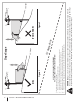
Section 2 — Important Safe Operation Practices Figure 1 line Figure 2 (TOO STEEP) 15° Slope WARNING! Slopes are a major factor related to tip-over and roll-over accidents which can result in severe injury or death. Do not operate machine on slopes in excess of 15 degrees. All slopes require extra caution. If you cannot back up the slope or if you feel uneasy on it, do not mow it. Always mow up and down slopes, never across the face of slopes. To check the slope, proceed as follows: 1.
3 Assembly & Set-Up Contents of Crate • Tractor (1) • Operator’s Manual (1) • Engine Operator’s Manual (1) • Hood Topper (1) – If Equipped • Dash Cap (1) – If Equipped • Steering Wheel Asm. (1) – If Equipped • Front Bumper (1) – If Equipped • Ignition Key (1) NOTE: This Operator’s Manual covers several models. Tractor features may vary by model. Not all features in this manual are applicable to all tractor models and the tractor depicted may differ from yours. 2.
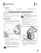
3. Rotate the seat into position and secure the seat into place with the previously removed shoulder screws and flange lock nuts. Be careful not to crimp or damage the wire harness while installing the seat. See Figure 3-3. Lower Deck Discharge Chute Deflector WARNING! Never operate the mower deck without the chute deflector installed and in the down position. 1. Check the mower deck for a shipping brace that may be holding the chute deflector upward for shipment.
Installing the Dash Cap (If necessary) To install the dash cap (1), line up the tabs (2) on the dash cap (1) with the holes in the upper dash as shown in Figure 3-7. Slide the tabs (2) into the holes in the upper dash and push forward on the dash cap (1) to lock into place. 2. Secure the steering wheel with the hex bolt from under the cap and torque to 18-22 ft./lbs. 3. Place the steering wheel cap over the center of the steering wheel and push downward until it “clicks” into place.
Adjusting the Seat 1. To adjust the position of the seat, lift the seat adjustment lever up. Slide the seat forward or rearward to the desired position; then release the adjustment lever. Make sure seat is locked into position before operating the tractor. See Figure 3-10. Remove the plastic cover, if present, from the positive battery terminal and attach the red cable to the positive battery terminal (+) with the bolt and hex nut. See Figure 3-11. Figure 3-11 2.
Settng the Deck Wheels Gas & Oil WARNING!: Keep hands and feet away from the discharge opening of the cutting deck. NOTE: The deck wheels are an anti-scalp feature of the deck and are not designed to support the weight of the cutting deck. Move the tractor on a firm and level surface, preferably pavement, and proceed as follows: 1. Check the tire pressure, make sure the pressure is correct and equal on all tires. 2. Make sure the deck is level, both front-to-back and side-toside.
4 Controls & Features Fuel Tank Cap EFI Ignition Module/ Service Minder & Hour Meter Throttle Control Lever Forward Drive Pedal Brake Pedal PTO Switch (If Equipped) Park Brake/Cruise Control Lever Reverse Drive Pedal PTO Handle Deck Lift Lever Storage Tray Cup Holder Electric PTO (If Equipped) Seat Adjustment Lever Manual PTO (If Equipped) Transmission Bypass Rod NOTE: This Operator’s Manual covers several models. Tractor features may vary by model.
Throttle Control The throttle control is located on the left side of the tractor’s dash panel. When set in a given position, a uniform engine speed will be maintained. Push the throttle control handle forward to increase the engine speed. The tractor is designed to operate with the throttle control in the fast position (full throttle) when the mower deck is engaged. Pull the throttle control handle rearward to decrease the engine speed.
PTO/Blade Engage Handle (Manual PTO tractors) The PTO/blade engage handle is located on the right fender. Activating the PTO engages power to the cutting deck or other (separately available) attachments. See the Operation section for information and instructions on using the PTO. Transmission Bypass Rod The transmission bypass rod is located at the rear of the tractor on the lower right section of the frame.
5 Operation WARNING! Avoid serious injury or death. Go up and down slopes, not across. Avoid sudden turns. Do not operate the tractor where it could slip or tip. If machine stops going uphill, stop the PTO and back down the hill safely. Keep safety devices (guards, shields and switches) in place and working. Remove objects that could be thrown by the blades. Know the location and function of all controls. Be sure the blades and the engine are stopped before placing hands or feet near blades.
2. Press the REVERSE CAUTION MODE button and hold for 3 seconds. The indicator light will flash for 3 seconds and will stay on when the REVERSE CAUTION MODE is activated. See Figure 5-1. 2. To travel FORWARD, slowly press the forward drive pedal forward until the desired speed is achieved. See Figure 5-2. Forward Service Minder & Hour Meter Reverse Ignition Key Reverse Caution Mode Button Figure 5-1 3. The indicator light above the REVERSE CAUTION MODE button will be ON while activated.
Engaging the Parking Brake Operating the Headlights NOTE: The parking brake must be set if the operator leaves the seat with the engine running or the engine will automatically shut off. To set the parking brake: The lamps are ON whenever the engine is on. If the ignition key is pressed for less than 1.5 seconds, the headlights will remain on for 15 seconds. The lamps turn OFF when the engine is turned OFF. 1. Press the brake pedal completely down with your left foot and hold it in that position.
2. Push the PTO handle forward into the ENGAGED (ON) position. See Figure 5-4. 7. When approaching the other end of the strip, slow down or stop before turning. 8. Align the mower with an edge of the mowed strip and overlap approximately 3”. 9. Direct the tractor on each subsequent strip to align with a previously cut strip. 10. To prevent rutting or grooving of the turf, if possible, change the direction that the strips are mowed by approximately 45° for the next and each subsequent mowing.
6 Maintenance & Adjustments Maintenance Schedule Before Each use Check & Clean Engine Cooling Fans for Debris Check Engine Oil Level Check Air Filter for Dirty, Loose or Damaged Parts After First 5 Hours Every 10 Hours Every 25 Hours Every 50 Hours P P P Prior to Storing See Engine Manual P P Clean Battery Terminals P P P P P P P Grease All Lubrication Points P P P P P Clean Hood/Dash Panel Louvers Check Intake Screen/Clean as Needed Check Blades/Sharpen or Replace as Needed Check Tire Pressu
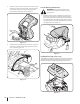
NOTE: This Operator’s Manual covers several models. Tractor features may vary by model. Not all features in this manual are applicable to all tractor models and the tractor depicted may differ from yours. 4. Remove the oil drain hose from the clip on the right side of the frame. See Figure 6-1. 5. Remove the oil drain hose plug from the end of the hose. See Figure 6-1. Drain the engine oil into the collection container. 6. After draining the oil, wipe any residual oil from the oil drain hose.
Cleaning the Tractor 12. Any fuel or oil spilled on the machine should be wiped off promptly. Do NOT allow debris to accumulate around the cooling fins of the engine, the transmission’s cooling fan or on any other part of the machine. Lubrication Smart Jet Your tractor’s deck is equipped with a water port on its surface as part of its deck wash system. Use the Smart Jet to rinse grass clippings from the deck’s underside and prevent the buildup of corrosive chemicals.
Deck Wheels 2. The wheels on the deck which are spherical shaped (50” and 54” decks have 4) are equipped with a grease fitting. Lubricate with a No. 2 multi-purpose grease applied with a grease gun after every 25 hours of tractor operation. Leveling the Deck (Side-to-Side) Pivot Points & Linkage Lubricate all the pivot points on the drive system, parking brake and lift linkage at least once a season with light oil. NOTE: It is not necessary to grease the steering pinion/sector gear interface.
2. Measure the distance from the outside of the left blade tip to the ground and the distance from the outside of the right blade tip to the ground. Both measurements taken should be 4”. If they’re not, proceed to the next step. 3. Using the right and left lift rods, raise or lower the necessary side of the deck until both sides are measured at 4” from the pavement. Adjusting the Deck Wheels WARNING!: Keep hands and feet away from the discharge opening of the cutting deck. 3.
7 Service Battery Fuse CALIFORNIA PROPOSITION 65 WARNING: Battery posts, terminals, and related accessories contain lead and lead compounds, chemicals known to the State of California to cause cancer and reproductive harm. Wash hands after handling. CAUTION: If removing the battery, disconnect the NEGATIVE (Black) wire from it’s terminal first, followed by the POSITIVE (Red) wire.
6. Slide the rod to the right to remove it. 11. NOTE: Be careful not to damage the wire harness when removing the rod. 7. Looking at the cutting deck from the left side of the tractor, locate the bow-tie pin on the rear left side of the deck. See Figure 7-4. Remove the bow pin that secures the PTO cable to the bracket on the deck, slide the PTO cable out of the bracket and unhook the spring from the idler bracket. See Figure 7-2. Figure 7-4 Figure 7-2 8.
Cutting Blades 4. WARNING! Shut the engine off and remove ignition key before removing the cutting blade(s) for sharpening or replacement. Protect your hands by using heavy gloves when grasping the blade To properly sharpen the cutting blades, remove equal amounts of metal from both ends of the blades along the cutting edges, parallel to the trailing edge, at a 25° to 30° angle. Always grind each cutting blade edge equally to maintain proper blade balance. See Figure 7-7.
3. Carefully remove the belt from around the idler pulleys and the spindle pulleys. 50” & 54” Decks WARNING! Avoid pinching injuries. Never place your fingers on the idler spring or between the belt and a pulley while removing the belt. 4. Route the new belt as shown in the applicable figure on the following pages. See Figure 7-8 for 42” decks, Figure 7-9 for 46” decks and Figure 7-10 for 50” & 54” decks.
8 Troubleshooting Problem Excessive vibration Uneven cut 30 Cause Remedy 1. Cutting blade loose. 1. Tighten blade and spindle. 2. Damaged, unbalanced or bent cutting blade. 2. Replace blade. 1. Deck not leveled properly. 1. Perform side-to-side deck adjustment. 2. Dull or damaged blade. 2. Sharpen or replace blade. 3. Uneven tire pressure. 3. Check and correct tire pressure in all four tires.
9 Replacement Parts Component Part Number and Description 954-05021 954-05027A Deck Belt, 42” Deck Drive Belt 942-04308 942-04308-X Blades, 42” Xtreme Blades, 42” 918-06976 Deck Spindle, 42 734-04155 734-0973 Front Deck Wheel Rear Deck Wheel 925-1707D Battery 951-14767 Gas Cap 746-05254 Throttle Control Cable Phone (800) 965-4CUB to order replacement parts or a complete Parts Manual (have your full model number and serial number ready).
Component Part Number and Description 625-05000 Ignition Key 631-04354B Discharge Chute Assembly, 42” 634-05160 Rear Wheel Assembly, 20.0 x 8.0 x 8.0 634-05159 Front Wheel Assembly, 15 x 6 x 6 951-10292 Spark Plug 937-05066 Air Filter 951-12690 Oil Filter Phone (800) 965-4CUB to order replacement parts or a complete Parts Manual (have your full model number and serial number ready). Parts Manual downloads are also available free of charge at www.cubcadet.com.
10 Attachments & Accessories Part No.
FEDERAL and/or CALIFORNIA EMISSION CONTROL WARRANTY STATEMENT YOUR WARRANTY RIGHTS AND OBLIGATIONS MTD Consumer Group Inc, the United States Environmental Protection Agency (EPA), and for those products certified for sale in the state of California, the California Air Resources Board (CARB) are pleased to explain the evaporative emission control system (ECS) warranty on your 2015-2016 small off-road equipment (outdoor equipment).
WARRANTED PARTS: The repair or replacement of any warranted part otherwise eligible for warranty coverage may be excluded from such warranty coverage if MTD Consumer Group Inc demonstrates that the outdoor equipment has been abused, neglected, or improperly maintained, and that such abuse, neglect, or improper maintenance was the direct cause of the need for repair or replacement of the part.
CUB CADET LLC MANUFACTURER’S LIMITED WARRANTY FOR XT1 AND XT2 SERIES TRACTORS IMPORTANT: To obtain warranty coverage owner must present an original proof of purchase and applicable maintenance records to the servicing dealer. Please see the operator’s manual for information on required maintenance and service intervals. In the U.S.A.