Safe Operation Practices • Set-Up • Operation • Maintenance • Service • Troubleshooting • Warranty Operator’s Manual Lawn Tractor — LTX1040 WARNING READ AND FOLLOW ALL SAFETY RULES AND INSTRUCTIONS IN THIS MANUAL BEFORE ATTEMPTING TO OPERATE THIS MACHINE. FAILURE TO COMPLY WITH THESE INSTRUCTIONS MAY RESULT IN PERSONAL INJURY. CUB CADET LLC, P.O. BOX 361131 CLEVELAND, OHIO 44136-0019 Printed In USA Form No.
1 To The Owner Thank You Thank you for purchasing a Lawn Tractor manufactured by Cub Cadet LLC. It was carefully engineered to provide excellent performance when properly operated and maintained. Please read this entire manual prior to operating the equipment. It instructs you how to safely and easily set up, operate and maintain your machine. Please be sure that you, and any other persons who will operate the machine, carefully follow the recommended safety practices at all times.
Important Safe Operation Practices 2 WARNING! This symbol points out important safety instructions which, if not followed, could endanger the personal safety and/or property of yourself and others. Read and follow all instructions in this manual before attempting to operate this machine. Failure to comply with these instructions may result in personal injury. When you see this symbol.
12. A missing or damaged discharge cover can cause blade contact or thrown object injuries. 13. Stop the blade(s) when crossing gravel drives, walks, or roads and while not cutting grass. 14. Watch for traffic when operating near or crossing roadways. This machine is not intended for use on any public roadway. 15. Do not operate the machine while under the influence of alcohol or drugs. 16. Mow only in daylight or good artificial light. 17. Never carry passengers. 18.
Children Service 1. Safe Handling of Gasoline: Tragic accidents can occur if the operator is not alert to the presence of children. Children are often attracted to the machine and the mowing activity. They do not understand the dangers. Never assume that children will remain where you last saw them. a. Keep children out of the mowing area and in watchful care of a responsible adult other than the operator. b. Be alert and turn machine off if a child enters the area. c.
Periodically check to make sure the blades come to complete stop within approximately (5) five seconds after operating the blade disengagement control. If the blades do not stop within the this time frame, your machine should be serviced professionally by an authorized MTD Service Dealer. Do not modify engine 4. Check brake operation frequently as it is subjected to wear during normal operation. Adjust and service as required. Notice Regarding Emissions 5.
Safety Symbols This page depicts and describes safety symbols that may appear on this product. Read, understand, and follow all instructions on the machine before attempting to assemble and operate. Symbol Description READ THE OPERATOR’S MANUAL(S) Read, understand, and follow all instructions in the manual(s) before attempting to assemble and operate DANGER— ROTATING BLADES Never carry passengers. Never carry children, even with the blades off.
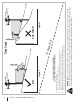
Section 2 — Important Safe Operation Practices Figure 1 line Figure 2 (TOO STEEP) 15° Slope WARNING! Slopes are a major factor related to tip-over and roll-over accidents which can result in severe injury or death. Do not operate machine on slopes in excess of 15 degrees. All slopes require extra caution. If you cannot back up the slope or if you feel uneasy on it, do not mow it. Always mow up and down slopes, never across the face of slopes. To check the slope, proceed as follows: 1.
3 Assembly & Set-Up Contents of Crate • One Lawn Tractor • • One Lawn Tractor Operator’s Manual • One Oil Drain Tube One Deck Wash Hose Coupler One Engine Operator’s Manual Tractor Set-Up 2. Moving The Tractor Manually To move the tractor manually, move the shift lever into the neutral position. Shipping Brace Removal WARNING! Make sure the lawn tractor’s engine is off, set the parking brake and remove the ignition key before removing the shipping brace. 1.
Connecting the Battery Cables Checking Tire Pressure WARNING! Do not overinflate tires. Check sidewall of tires for maximum psi. Equal tire pressure should be maintained at all times. CALIFORNIA PROPOSITION 65 WARNING! Battery posts, terminals, and related accessories contain lead and lead compounds, chemicals known to the State of California to cause cancer and reproductive harm. Wash hands after handling.
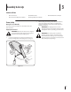
Adjusting the Seat Gas and Oil To adjust the position of the seat, pull up and hold the seat adjustment lever. Slide the seat forward or rearward to the desired position; then release the adjustment lever. Make sure seat is locked into position before operating the tractor. See Fig. 3-4. The fuel tank is located under the hood and has a capacity of 3.3 gallons. Remove the fuel cap by turning it counterclockwise. Use only clean, fresh (no more than 30 days old), unleaded gasoline.
4 Controls and Features Systems Indicator Monitor Fuel Tank Cap Ignition Switch Module Throttle/Choke Control Fuel Level Indicator Brake Pedal Seat Adjustment Lever Shift Lever Assembly Parking Brake Cruise Control Lever Lever Drive Pedal Deck Lift Lever PTO (Blade Engage) Handle Cup Holder Figure 4-1 Lawn Tractor controls and features are illustrated in Fig. 4-1 and described on the following pages.
Deck Lift Lever Systems Indicator Monitor/Hour Meter LCD Found on your tractor’s right fender, the deck lift lever is used to change the height of the cutting deck. To use, move the lever to the left, then place in the notch best suited for your application.
Fuel Level Indicator The Fuel Level Indicator is located on the left side of the tractor’s dash and indicates the amount of fuel in the gas tank. PTO / Blade Engage Handle Activating the PTO engages power to the cutting deck or other (separately available) attachments. Push forward on the PTO/Blade Engage handle to activate it. Pull the PTO/ Blade Engage handle back to disengage the power to the cutting deck or other (separately available) attachments.
5 Operation Starting the Engine WARNING! Do not operate the tractor if the interlock system is malfunctioning. This system was designed for your safety and protection. TO AVOID SERIOUS INJURY OR DEATH • • • • • • • • • GO UP AND DOWN SLOPES, NOT ACROSS. AVOID SUDDEN TURNS. DO NOT OPERATE THE UNIT WHERE IT COULD SLIP OR TIP. IF MACHINE STOPS GOING UPHILL, STOP BLADE(S) AND BACK DOWNHILL SLOWLY. KEEP SAFETY DEVICES (GUARDS, SHIELDS, AND SWITCHES, ETC.) IN PLACE AND WORKING.
Driving The Tractor Reverse Caution Mode WARNING! Avoid sudden starts, excessive speed and sudden stops. The REVERSE CAUTION MODE position of the key switch module allows the tractor to maneuver in reverse with the blades (PTO) engaged. NOTE: Mowing in reverse is not recommended. 1. Lightly press the brake pedal to release the parking brake. Move the throttle lever into the FAST (rabbit) position. 2. To travel FORWARD, slowly press the drive pedal forward until the desired speed is achieved. See Fig.
Driving On Slopes Setting The Cruise Control Refer to the SLOPE GAUGE on page 8 to help determine slopes where you may operate the tractor safely. WARNING! Do not mow on inclines with a slope in excess of 15 degrees (a rise of approximately 2-1⁄2 feet every 10 feet). The tractor could overturn and cause serious injury. WARNING! Never engage the cruise control lever while traveling in reverse. To set the cruise control: 1.
Engaging the PTO Engaging the PTO transfers power to the cutting deck or other (separately available) attachments. To engage the PTO: 1. Move the Throttle/Choke control lever to the FAST (rabbit) position. 2. Push the PTO/Blade Engage lever forward into the engaged (ON) position. NOTE: Always operate the tractor with the Throttle/ Choke control lever in the FAST (rabbit) position for the most efficient use of the cutting deck or other (separately available) attachments.
6 Maintenance & Adjustments Maintenance Schedule Before Each use Every 10 Hours Check Air Filter for Dirty, Loose or Damaged Parts Every 50 Hours Every 100 Hours P Clean Hood/Dash Louvers Check Engine Oil Level Every 25 Hours Prior to Storing P P P P Clean and Re-oil Air Filter’s Foam Precleaner P Replace Air Filter Element P Change Engine Oil and Replace Oil Filter Clean Battery Terminals P P P P P Lube Front Axles and Rims Clean Engine Cooling Fins Lube Front Deck Wheels Lube Deck Spindl
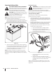
3. Pop open the protective cap on the end of the oil drain valve to expose the drain port. See Fig 6-1. Battery CALIFORNIA PROPOSITION 65 WARNING! Battery posts, terminals, and related accessories contain lead and lead compounds, chemicals known to the State of California to cause cancer and reproductive harm. Wash hands after handling. The battery is sealed and is maintenance-free. Acid levels cannot be checked and fluid can not be added.
4. Attach the hose coupler to the water port on your deck’s surface. See Fig. 6-2. Lubrication WARNING! Before lubricating, repairing, or inspecting, always disengage PTO, set parking brake, stop engine and remove key to prevent unintended starting. Front Wheels Each of the front wheel axles and rims is equipped with a grease fitting. See Fig. 6-3. Lubricate with a No. 2 multi-purpose grease applied with a grease gun after every 25 hours of tractor operation. Figure 6-2 5. Turn the water on. 6.
Adjustments WARNING! Shut the engine off, remove the ignition key and engage the parking brake before making adjustments. Protect your hands by using heavy gloves when handling the blades. Determine the approximate distance necessary for proper adjustment and proceed, if necessary. 1. Locate the hex lock nut on the end of the deck hanger rod. See Fig. 6-4. NOTE: Check the tractor’s tire pressure before performing any deck leveling adjustments.
Leveling the Deck (Side to Side) Steering Adjustment If the cutting deck appears to be mowing unevenly, a side to side adjustment can be performed. Adjust if necessary as follows: If the tractor turns tighter in one direction than the other, or if the ball joints are being replaced due to damage or wear, the steering drag links may need to be adjusted. 1. 2. 3.
7 Service Cutting Deck Removal 1. Place the PTO/Blade Engage knob in the disengaged (OFF) position and engage the parking brake. 2. Lower the deck by moving the deck lift lever into the bottom notch on the right fender. 3. Locate the PTO clutch under the front of your tractor. See Fig. 7-1.
6. Pull the deck support pin outward to release the deck from the deck lift arm. See Fig. 7-3. Deck Lift Arm Deck Support Pin Figure 7-5 Figure 7-3 7. Repeat the above steps on the tractor’s right side. 8. Move the deck lift lever into the top notch to raise the deck lift arms up and out of the way. 9. Carefully remove the deck engage cable from the rear of the cutting deck by removing the bow-tie cotter clip that secures it. Remove the spring from the deck idler bracket. See Fig. 7-4.
4. Carefully remove the deck belt from around the two spindle pulleys and the two deck idler pulleys. See Fig. 7-6. 5. To place the new belt, begin by routing the belt around the two outer spindle pulleys as shown in Fig. 7-7. 10. Place the belt into the engine pulley. See Fig. 7-8. Belt Engine Pulley Figure 7-8 11. Figure 7-7 26 6. Then route the belt around the two deck idler pulleys as shown in Fig. 7-7. 7. Reinstall the belt keeper rod loosened earlier. 8.
2. Place a block of wood between the center deck housing baffle and the cutting blade to act as a stabilizer. See Fig. 7-9. 3. Remove the hex flange nut that secures the blade to the spindle assembly. See Fig. 7-9. 5. Test the blade’s balance using a blade balancer. Grind metal from the heavy side until it balances evenly.
Tires Charging WARNING! Batteries give off an explosive gas while charging. Charge the battery in a well ventilated area and keep away from an open flame or pilot light as on a water heater, space heater, furnace, clothes dryer or other gas appliances. CAUTION: When charging your tractor’s battery, use only a charger designed for 12V lead-acid batteries. Read your battery charger’s Owner’s Manual prior to charging your tractor’s battery. Always follow its instructions and heed its warnings.
8 Troubleshooting Problem Engine fails to start Cause Remedy 1. PTO/Blade Engage lever engaged. 1. Place lever in disengaged (OFF) position. 2. Parking brake not engaged. 2. Engage parking brake. 3. Spark plug wire disconnected. 3. Connect wire to spark plug. 4. Throttle/Choke control lever not in correct starting position. 4. Place Throttle/Choke lever to FAST position. 5. Fuel tank empty, or stale fuel. 5. Fill tank with clean, fresh (less than 30 days old) gas. 6. Blocked fuel line. 6.
9 Replacement Parts Component Part Number and Description 759-3336 Spark Plug (Champion RC12YC) KH-20-883-02-S1 Kohler Air Filter Element KH-12-050-01-S Kohler Oil Filter KH-25-050-21-S Kohler Fuel Filter 954-04060B Drive Belt (Mower Deck) 942-04312 2-in-1 Deck Blade 925-1707D Battery 918-04822A Deck Spindle Phone (800) 965-4CUB to order replacement parts or a complete Parts Manual (have your full model number and serial number ready).
Component Part Number and Description 734-04155 Deck Wheel (Front) 734-0973 Deck Wheel (Rear) 951-12179A 951-10947 Fuel Tank Cap Fuel Tank Cap (California Models) 946-04617 Throttle/Choke Control Lever & Cable 925-2054A Ignition Key (Plastic) 631-04344 Discharge Chute Assembly Phone (800) 965-4CUB to order replacement parts or a complete Parts Manual (have your full model number and serial number ready). Parts Manual downloads are also available free of charge at www.cubcadet.com.
10 Attachments & Accessories The following attachments and accessories are compatible for Cub Cadet LTX 1040. See your Cub Cadet dealer or the retailer from which you purchased your tractor for information regarding price and availability. CAUTION: Cub Cadet Series 1000 lawn tractors are NOT designed for use with any type of ground-engaging attachments (e.g. tiller or moldboard plow). Use of this type of equipment WILL void the tractor’s warranty.
Notes 11 33
FEDERAL and/or CALIFORNIA EMISSION CONTROL WARRANTY STATEMENT YOUR WARRANTY RIGHTS AND OBLIGATIONS MTD Consumer Group Inc, the United States Environmental Protection Agency (EPA), and, for those products certified for sale in the state of California, the California Air Resources Board (CARB) are pleased to explain the emission (evaporative and/or exhaust) control system (ECS) warranty on your outdoor 2006 and later small off-road spark-ignited engine and equipment (outdoor equipment engine) In California, n
WARRANTED PARTS: The repair or replacement of any warranted part otherwise eligible for warranty coverage may be excluded from such warranty coverage if MTD Consumer Group Inc demonstrates that the outdoor equipment engine has been abused, neglected, or improperly maintained, and that such abuse, neglect, or improper maintenance was the direct cause of the need for repair or replacement of the part.
CUB CADET LLC MANUFACTURER’S LIMITED WARRANTY FOR SERIES 1000 & SERIES 1500 TRACTORS IMPORTANT: To obtain warranty coverage owner must present an original proof of purchase and applicable maintenance records to the servicing dealer. Please see the operator’s manual for information on required maintenance and service intervals. In the U.S.A.: Check your Yellow Pages, or contact Cub Cadet LLC at P.O. Box 361131, Cleveland, Ohio 44136-0019, call 1-877-282- 8684 or log on to our website at www.cubcadet.com.
Medidas importantes de seguridad • Configuración • Funcionamiento • Mantenimiento • Servicio • Solución de problemas • Garantía Manual del Operador Tractor Corta Césped — LTX1040 ADVERTENCIA LEA Y SIGA TODAS LAS INSTRUCCIONES DE ESTE MANUAL ANTES DE PONER EN FUNCIONAMIENTO ESTA MÁQUINA. SI NO RESPETA ESTAS INSTRUCCIONES PUEDE PROVOCAR LESIONES PERSONALES. CUB CADET LLC, P.O.
1 Al propietario Gracias Gracias por comprar una Cub Cadet máquina quitanieve. La misma ha sido diseñada cuidadosamente para brindar excelente rendimiento si se la opera y mantiene correctamente. las especificaciones de los productos, los diseños y el equipo estándar sin previo aviso y sin generar responsabilidad por obligaciones de ningún tipo. Por favor lea todo este manual antes de operar el equipo. Le indica cómo configurar, operar y mantener la máquina con seguridad y fácilmente.
2 Medidas importantes de seguridad ADVERTENCIA: La presencia de este símbolo indica que se trata de instrucciones importantes de seguridad que se deben respetar para evitar poner en peligro su seguridad personal y/o material y la de otras personas. Lea y siga todas las instrucciones de este manual antes de poner en funcionamiento esta máquina. Si no respeta estas instrucciones puede provocar lesiones personales. Cuando vea este símbolo.
10. Esté atento a la cortadora y a la dirección de la descarga de los aditamentos y no apunte a nadie. Nunca opere la cortadora de césped sin que estén en su lugar apropiado la cubierta de descarga o el colector de recortes de césped. 11. No ponga las manos o los pies cerca de las piezas rotatorias o debajo de la plataforma de corte. El contacto con las cuchillas puede producir la amputación de manos y pies. 12.
6. 7. No cambie a transmisión neutral para descender. El exceso de velocidad puede hacer que el operador pierda el control de la máquina, ocasionando lesiones graves e incluso la muerte. No remolque cargas pesadas detrás de los aditamentos (carrito de basura cargado, podadora de rodillos, etc) en pendientes mayores de 5 grados.
2. 3. 4. 5. 6. 7. 8. 9. 10. 11. 12. 13. 14. Antes de limpiar, reparar o inspeccionar la máquina, compruebe que la(s) cuchilla(s) y todas las partes en movimiento se hayan detenido. Desconecte el cable de la bujía y póngalo haciendo masa contra el motor para evitar que se encienda accidentalmente. Revise periódicamente para asegurarse que las cuchillas se detengan por completo en aproximadamente cinco (5) segundos después de accionar el control de desenganche de la(s) cuchilla(s).
Safety Symbols This page depicts and describes safety symbols that may appear on this product. Read, understand, and follow all instructions on the machine before attempting to assemble and operate. Symbol Description LEA EL MANUAL(S) DEL OPERADOR leído, entienda, y siga todas las instrucciones en el manual(s) antes de procurar montar y funcionar PELIGRO— DÉ EL CORTE DE PIE Nunca transporte pasajeros. Nunca transporte niños, aún con la cuchilla apagada. PELIGRO— DÉ EL CORTE DE PIE Retroceda lentamente.
Section 2 — Medidas importantes de seguridad Figura 1 tinua iscon nea d 15° lí 15° Pendiente ADVERTENCIA! Las pendientes son un factor importante relacionado con un vuelco y renovación de los accidentes que pueden provocar lesiones graves o la muerte. No utilice la máquina en pendientes de más de 15 grados. Todos pendientes requiere mayor precaución. Si no puede retroceder en la pendiente o si se siente inseguro en ella, no la recorte.
3 Montaje y Configuración Contenido del cajón • Un tractor corta césped • Un tubo de drenaje de aceite • Un Manual del operador del tractor corta césped • Un Manual del operador del motor Configuración del tractor Movimiento manual del tractor Para mover el tractor manualmente, mueva la palanca de cambios a la posición neutral.
Instalación del cable de la baterías Control de la presión de los neumáticos PROPUESTA 65 DE CALIFORNIA ADVERTENCIA! Los postes de la batería, terminales y accesorios relacionados contienen plomo y compuestos químicos, conocidos por el Estado de California que causan cáncer y daños en la reproducción. Lávese las manos después de la manipulación.
Ajuste del asiento Gasolina y aceite Para ajustar la posición del asiento, tire hacia arriba y mantenga la sede de ajuste. Deslice el asiento hacia adelante o hacia atrás a la posición deseada y luego suelte la palanca de ajuste. Asegúrese de que está bloqueado asiento en su posición antes de operar el tractor. Ver Fig. 6-4. El tanque de combustible está ubicado debajo del guardabarros y posee una capacidad de tres galones y medio.
4 Controles y Características Monitor del indicador de sistemas Tapón del tanque de combustible Módulo del interruptor de encendido Control del regulador/cebador Indicador de nivel de combustible Pedal de freno Palanca de ajuste del asiento Palanca de freno de mano Montaje de la palanca de cambios Pedal de la transmisión Palanca de control de crucero Palanca de elevación de la plataforma Manija de potencia de arranque (PTO)/ enganche de cuchilla Portacubeta Figura 4-1 Los controles y característic
Palanca de elevación de la plataforma Monitor del indicador de sistemas / Pantalla LCD del medidor horario Ubicada en el guardabarros derecho del tractor, la palanca de elevación de la plataforma se utiliza para cambiar la altura de la plataforma de corte. Para utilizarla, mueva la palanca hacia la izquierda, luego colóquela en la muesca que mejor se adapte a la aplicación deseada.
Indicador de nivel de combustible Freno de mano / palanca de control de crucero El indicador de nivel de combustible está ubicado a la derecha del panel de instrumentos del tractor e indica la cantidad de combustible en el tanque. Localizada en el centro del panel de instrumentos del tractor debajo del volante, el freno de mano/palanca de control de crucero se utiliza para conectar el freno de mano y el control de crucero.
5 Funcionamiento ADVERTENCIA PARA EVITAR LESIONES PERSONALES GRAVES O LA MUERTE • EN LAS PENDIENTES PODE HACIA ARRIBA Y HACIA ABAJO, NO DE FORMA TRANSVERSAL. • EVITE MANIOBRAS DE GIRO BRUSCAS. • NO OPERE LA UNIDAD EN ÁREAS DONDE PUEDE DERRAPAR O TROPEZAR • SI LA MÁQUINA DEJA DE SUBIR LA PENDIENTE, DETENGA LA(S) CUCHILLA(S) Y RETROCEDA LENTAMENTE CUESTA ABAJO • MANTENGA TODOS LOS DISPOSITIVOS DE SEGURIDAD (PROTECCIONES, ESCUDOS, INTERRUPTORES, ETC.) EN SU LUGAR Y EN CORRECTO FUNCIONAMIENTO.
Conducción del tractor ¡ADVERTENCIA! Evite arrancar súbitamente, desarrollar excesiva velocidad y detenerse de repente. 1. Presione levemente el pedal del freno para liberar el freno de mano. Mueva la palanca del regulador a la posición FAST (VELOCIDAD RÁPIDA, representada por una liebre). 2. Para conducir hacia adelante, presione suavemente la parte superior del pedal de transmisión hacia adelante hasta que se alcance la velocidad deseada. Vea la Fig. 5-1.
Operación en pendientes Activación del control de crucero Consulte la sección INDICADOR DE PENDIENTE en la página 8 para determinar en qué pendientes puede operar el tractor de manera segura. ¡ADVERTENCIA! Nunca enganche la palanca de control de crucero mientras se desplaza en marcha atrás. ¡ADVERTENCIA! No corte el césped en inclinaciones Para colocar el control de crucero: mayores a 15 grados (elevación aproximada de 2-1⁄2 pies cada 10 pies). El tractor podría voltearse y causar lesiones severas.
Conexión de potencia de arranque (PTO) Al conectar la potencia de arranque (PTO) se suministra alimentación a la plataforma de corte o a otros accesorios (disponibles por separado). Para conectar la PTO: 1. Mueva la palanca de control del regulador/cebador a la posición FAST (VELOCIDAD RÁPIDA, representada por una liebre). 2. Empuje hacia adelante la palanca de potencia de arranque (PTO) (enganche de cuchilla) hasta la posición ON (conectada).
6 Mantenimiento y Ajustes Calendario de mantenimiento Antes de cada uso Controle el filtro de aire para ver si hay piezas sucias, sueltas o dañadas Cada 25 horas Cada 50 horas Cada 100 horas Antes de almacenar P Limpie el capó/los respiraderos Inspeccione el nivel de aceite del motor Cada 10 horas P P P Limpie y vuelva a lubricar el depurador de espuma del filtro de aire P P Reemplace el elemento del filtro de aire Cambie el aceite del motor y reemplace el filtro de aceite Limpie los bornes de
3. Abra el tapón protector en el extremo de la válvula de drenaje de aceite para dejar expuesto el orificio de drenaje. Vea la Fig. 6-1. Batería ¡ADVERTENCIA PROPOSICIÓN 65 DE CALIFORNIA! Los bornes de la batería y los accesorios afines contienen plomo y compuestos de plomo, sustancias químicas que según lo establecido por el Estado de California causan cáncer y daños en el sistema reproductivo. Lávese las manos después de estar en contacto con estos componentes.
3. Una el acople de la manguera al puerto de agua que se encuentra en la superficie de la plataforma. Vea la Fig. 6-2. Lubricación ¡ADVERTENCIA! Antes de realizar tareas de mantenimiento, reparaciones o inspecciones, desconecte la potencia de arranque (PTO), coloque el freno de mano, apague el motor y retire la llave, para evitar que alguien encienda accidentalmente el motor. Ruedas delanteras Cada uno de los ejes y llantas de la rueda delantera viene equipado con un accesorio de engrase.
Ajustes Determine la distancia aproximada necesaria para un ajuste adecuado y, de ser necesario, proceda. ¡ADVERTENCIA! Apague el motor, retire la llave de encendido y coloque el freno de mano antes de realizar ajustes. Proteja sus manos utilizando guantes pesados cuando maneje las cuchillas. NOTA: Revise la presión de los neumáticos del tractor antes de realizar cualquier nivelación de la plataforma.
Nivelación de la plataforma (lado a lado) Ajuste del volante Si la plataforma de corte estuviera realizando el corte de césped de forma despareja, puede realizarse un ajuste lado a lado. De ser necesario, realice un ajuste de la siguiente manera: Si le cuesta girar el tractor en una dirección más que en la otra, o si se reemplazan las juntas de rótula debido a daños o desgaste, puede ser necesario ajustar las barras de acoplamiento del volante. 1.
7 Servicio Extracción de la plataforma de corte NOTA: Si hay demasiada tensión en la correa para que sea quitada fácilmente de la polea del motor, inserte cuidadosamente” llave de trinquete de impulsión un 3⁄8 (fije para apretar) en la perforación rectangular encontrada en el soporte más ocioso de la cubierta izquierda y gírelo hacia el derecho del tractor para relevar la tensión en la correa. Vea fig. 7-2. Para extraer la plataforma de corte, proceda de la siguiente manera: 1.
6. Tire hacia afuera el pasador de soporte de la plataforma para separar la misma del brazo de elevación de la plataforma. Vea la Fig. 7-3. 10. Deslice suavemente la plataforma de corte hacia la parte delantera del tractor y con cuidado guíe los ganchos de la plataforma para extraerlos de la varilla estabilizadora de la plataforma. Vea la Fig. 7-5. Brazo de elevación de la plataforma Pasador de soporte de la plataforma Figura 7-3 7. Repita los pasos anteriores del lado derecho del tractor. 8.
Cuchillas de corte 4. ¡ADVERTENCIA! Apague el motor y extraiga la llave de contacto antes de retirar las cuchillas de corte para afilado o reemplazo. Proteja sus manos utilizando guantes reforzados cuando maneje las cuchillas. PRECAUCIÓN: Si el borde de corte de la cuchilla ha sido afilado previamente o si existe una separación de metal, reemplace las cuchillas por otras nuevas.
Batería ¡ADVERTENCIA PROPOSICIÓN 65 DE CALIFORNIA! Los bornes de la batería y los accesorios afines contienen plomo y compuestos de plomo, sustancias químicas que según lo establecido por el Estado de California causan cáncer y daños en el sistema reproductivo. Lávese las manos después de estar en contacto con estos componentes. PRECAUCIÓN: Si extrae la batería, desconecte primero el cable NEGATIVO (negro) de su borne y a continuación el cable POSITIVO (rojo).
Cambio de la correa de la plataforma ¡ADVERTENCIA! Apague el motor y extraiga la llave de contacto antes de retirar las cuchillas de corte para afilado o reemplazo. Proteja sus manos utilizando guantes reforzados cuando maneje las cuchillas y las poleas. ¡ADVERTENCIA! Las correas en V del tractor están diseñadas especialmente para que se engranen y desengranen sin riesgos.
8 Solución de Problemas Problema El motor no arranca El motor funciona de manera errática Causa Solución 1. Palanca de potencia de arranque (PTO) /enganche de cuchilla conectada. 1. Coloque la palanca en la posición de desconexión (OFF). 2. No está colocado el freno de mano. 2. Coloque el freno de mano. 3. Se ha desconectado el cable de la bujía. 3. Conecte el cable a la bujía. 4. La palanca de control del regulador/cebador no está en la posición de arranque correcta. 4.
Piezas de reemplazo Componente 9 Número de pieza y Descripción 759-3336 Bujía (Champion RC12YC) KH-20-883-02-S1 Limpiador de Aire Elemento con Pre-Filtro KH-12-050-01-S Filtro de Aceite KH-25-050-21-S Filtro de Combustible 954-04060B Correa de Tracción (Plataforma de Corte) 942-04312 2-in-1 Cuchilla de Plataforma 918-04822A Husilla de Plataforma 734-04155 Rueda de Plataforma (Frente) Llame por teléfono al (800) 965-4CUB para solicitar piezas de reemplazo o un Manual de Piezas de Repuesto compl
Componente Número de pieza y Descripción 734-0973 Rueda de Plataforma (Trasera) 925-1707D Batería 951-12179A 951-10947 Tapa del Tanque de Combustible Tapa del Tanque de Combustible (California) 946-04617 Acelerador y Palanca de Control de Choke & Cable 925-2054A Llave de Encendido 631-04344 Asamblea de Canal de Descarga Llame por teléfono al (800) 965-4CUB para solicitar piezas de reemplazo o un Manual de Piezas de Repuesto completo (tenga el número de modelo y número de serie de su máquina a m
10 Aditamentos y Accesorios Los siguientes aditamentos y accesorios son compatibles con el LTX1040. Llame (800) 965-4CUB para la información con respecto a la compatibilidad, el precio y la disponibilidad (tener su número de modelo completo y número de serie). PRECAUCIÓN: Cub Cadet tractores del césped de la serie 1000 no están diseñados para su uso con cualquier tipo de acoplamiento de tierra adjuntos(por ejemplo, caña o arado de vertedera).
Notas 11 69
DECLARACIÓN FEDERAL y/o DE CALIFORNIA SOBRE GARANTÍAS EN EL CONTROL DE EMISIONES SUS DERECHOS Y OBLIGACIONES EN CUANTO A LA GARANTÍA MTD Consumer Group Inc, la Agencia de Protección Medioambiental de los Estados Unidos (EPA), y para aquellos productos certificados para su venta en el estado de California, el Departamento de los Recursos del Aire de California (CARB) se complacen en explicar la garantía que cubre al sistema de control (ECS) de emisiones (evaporativas y/o de escape) de su equipo y motor (moto
8. Durante la totalidad del período de garantía del motor y equipo para todo terreno arriba mencionado, MTD Consumer Group Inc mantendrá un suministro de piezas bajo garantía suficiente para satisfacer la demanda esperada de tales piezas. 9. Cualquier pieza de reemplazo se podrá usar para el cumplimiento del mantenimiento o las reparaciones bajo garantía y se suministrarán sin cargo para el propietario. Dicho uso no reducirá las obligaciones de garantía de MTD Consumer Group Inc. 10.
GARANTÍA LIMITADA DEL FABRICANTE CUB CADET LLC PARA TRACTORES DE SERIE 1000 Y SERIE 1500 IMPORTANTE: Para obtener cobertura de garantía, el propietario debe presentar una evidencia original de la compra y los registros de mantenimiento correspondientes al centro de servicio técnico autorizado del distribuidor. Consulte el manual del operador para obtener información sobre los intervalos de mantenimiento y servicio requeridos.