SERVICE MANUAL (DOMESTIC) IMPINGER CONVEYOR OVENS MODEL 1450,1451 WITH PUSH BUTTON CONTROLS Lincoln Foodservice Products, Inc. 1111 North Hadley Road P.O. Box 1229 Fort Wayne, Indiana 46801-1229 Phone : (800) 374-3004 • Fax: (260) 436-0735 Technical Service Hot Line (800) 678-9511 www.lincolnfp.
SEQUENCE OF OPERATION IMPINGER ADVANTAGE SERIAL NUMBER N28654 AND ABOVE (OVENS WITH PUSH BUTTON CONTROLS) MODEL 1450 MODEL 1451 POWER SUPPLY CONTROL BOX AUTO COOL DOWN MAIN FAN CIRCUIT BURNER CIRCUIT IGNITION CONTROL TEMPERATURE CONTROL CONVEYOR DRIVE 2 120VAC 120VAC 60 HZ. 60 HZ. NAT. GAS LP GAS Electrical power is supplied to the oven by a three conductor cordset. Voltage from the black conductor to the white conductor is 120VAC. The white conductor is neutral. The green conductor is ground.
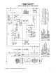
SCHEMATIC DIAGRAM MODEL 1450, 1451 SERIAL NUMBER N28654 AND ABOVE Impinger I – 1450 Series Service Manual - Domestic 3
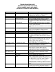
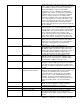
TROUBLESHOOTING GUIDE IMPINGER ADVANTAGE GAS OVENS SERIAL NUMBER N28654 AND ABOVE (OVENS WITH PUSH BUTTON CONTROLS) SYMPTOM Oven fan will not run POSSIBLE CAUSE Incoming power supply Fuse, 10 Amp Fuse holder Switch, oven power Motor, main fan No control box cooling Incoming power supply Fuse, 10 Amp Fuse holder Switch, oven power Cooling fan No automatic control box cooling Incoming power supply Cooling fan thermostat Control box cooling fan continues to run Cooling fan thermostat Oven will not he
Burner transformer Centrifugal switch of burner blower motor Ignition control No pilot flame Pilot shut-off valve Pilot tube Pilot orifice Burner igniter Pilot flame, but no main flame NOTE: Flame should be at this time Control transformer Oven control Impinger I – 1450 Series Service Manual - Domestic on not running, check for opens, shorts or grounds. WITH POWER OFF: Turn motor to check for locked rotor. Replace burner blower motor as needed.
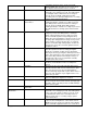
Thermocouple Oven control Thermocouple Oven control Temperature regulation valve Intermittent heating Thermal/overload of main fan and burner blower motors Conveyor will not run Incoming power supply Fuse, 10 Amp Fuse holder Switch, oven power 6 the display, replace oven control. If there is a read-out on the control, set the control to maximum temperature (see Installation operations manual for temperature adjustment).
Control transformer Conveyor motor Capacitor, conveyor motor Switch, conveyor reversing Oven control Conveyor motor runs, but there is no speed display NOTE: Display will indicate “BELT JAM” Oven control Conveyor motor Oven control Impinger I – 1450 Series Service Manual - Domestic Check for 120VAC supply to the primary of the control transformer. If no voltage is present, trace wiring back to the oven power switch. If voltage is present, check foe 24VAC at the transformer secondary.
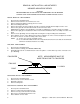
REMOVAL, INSTALLATION & ADJUSTMENTS IMPINGER ADVANTAGE SERIES CAUTION! BEFORE REMOVING OR INSTALLING ANY COMPONENT IN THE IMPINGER OVEN BE SURE TO DISCONNECT ELECTRICAL POWER AND GAS SUPPLY MOTOR, MAIN FAN - REPLACEMENT 1. 2. 3. 4. 5. 6. 7. 8. 9. Shut off power at main breaker. Remove louvered motor cover from back of oven. Remove wireway by taking out the (5) five hex screws. Disconnect wiring from motor. Remove the twelve (12) hex head bolts from the oven back and slide back straight out of the oven.
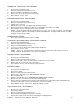
THERMOSTAT, COOLING FAN - REPLACEMENT 1. 2. 3. 4. 5. Shut off power at main breaker. Remove control panel top and front cover. Remove lead wires and mark for reassembly. Remove two (2) screws and remove thermostat. Reassemble in reverse order. BURNER BLOWER MOTOR - REPLACEMENT 1. 2. 3. 4. 5. 6. Shut off power at main breaker. Remove control panel top and front cover. Unplug motor connector. Remove three (3) screws from blower tube at burner housing.
6. 7. 8. 9. 10. Remove incoming nipple. Remove pilot tube assembly from control valve. Disconnect pipe union just above solenoid valve. Disconnect wiring from control valve making note of wire numbers and location. Remove piping from old valve for installation on new valve. Reassemble in reverse order - after assembly is complete, be sure to check manifold pressure (3.5" W.C. NAT GAS 10" W.C. LP) and adjust if necessary.
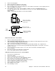
BURNER IGNITOR - REPLACEMENT 1. 2. 3. 4. 5. 6. Shut off power at main breaker. Remove control panel top and front cover. Remove burner assembly. (SEE "BURNER ASSY.") Remove pilot shield and pilot shield extension. Remove burner ignitor. Reassemble in reverse order (spark gap approx. .100 in. or 2.5 mm) NOTE: Be sure to reconnect burner ignitor cable to ignition control. THERMOCOUPLE - REPLACEMENT 1. 2. 3. 4. 5. Shut off power at main breaker. Remove control panel top and front cover.
REVERSING CONVEYOR DIRECTION All ovens leaving our plant are wired to operate conveyors from left to right. To reverse conveyor direction, use the following procedure. 1. 2. 3. Shut off power at oven switch. Set conveyor reversing switch in the other position. Turn oven “on” and check for proper operation. MAIN ORIFICE - REPLACEMENT 1. 2. 3. 4. 5. 6. 7. Shut off power at main breaker. Remove control panel top and front panel. Remove gas control valve assy. Remove two (2) nuts from burner orifice bracket.
This page intentionally left blank.
GENERAL VIEW ADVANTAGE SERIES LETTER A B C D E F G H J K L M N O P Q R S T U V W X Y Z * AA BB CC DD EE FF GG HH JJ KK LL MM NN OO PP QQ 14 PART NUMBER 369003 369110 369337 369929 369828 369209 369310 369308 369334 369309 350638 369311 369336 369906 370110 369157 1534 369057 369643 1009 369062 369140 369903 369141 369139 369058 369211 369203 369749 369204 369373 369748 369328 369052 369030 369904 369053 369055 369218 369926 369925 369927 DESCRIPTION Door hinge Access window assembly Retainer (old style)
Impinger I – 1450 Series Service Manual - Domestic 15
CONTROL BOX – 1450, 1451 S/N N28654 and ABOVE LETTER A B C D E F G H I J K L M N O P Q R S T U V W Y Z AA BB CC DD EE FF GG 16 PART # 369263 369344 369398 370059 369072 369099 369144 369202 369076 369075 369142 369366 369399 369400 370362 370368 369158 369124 369393 370359 369507 369331 369531 370352 370418 370355 370354 369805 370363 369537 369129 369166 353014 DESCRIPTION Gas Valve Pilot Shut Off Valve Solenoid Valve Nat/LP Manifold, Burner Main Orifice, Nat. Main Orifice, L.P.
Impinger I – 1450 Series Service Manual - Domestic 17
OVEN BACK ADVANTAGE SERIES GAS AND ELECTRIC LETTER A B C D E F G H J K M 18 PART NUMBER 369808 370140 369800 369214 369033 369215 369192 369306 369646 369647 369213 369547 369287 369315 369122 DESCRIPTION Cover, motor (gas ovens) Cover, motor (electric ovens) Motor, main fan (60 Hz.) Motor, main fan (50 Hz.) Motor clamp Motor support assembly Capacitor, 7.
Impinger I – 1450 Series Service Manual - Domestic 19
CONVEYOR 1450 SERIES LETTER A B C D E F G H J K L M 20 PART NUMBER 369830 369816 370092 369825 369813 369314 369812 369160 369814 369811 369161 369806 370050 369162 DESCRIPTION Complete conveyor assembly Conveyor belt Conveyor belt, 1 foot section Retaining ring Conveyor bearing block Roll, conveyor, notched Conveyor idler shaft Conveyor pan stop Connecting link Conveyor drive shaft Roller chain sprocket Crumb pan Conveyor frame Drive chain Impinger I – 1450 Series Service Manual - Domestic
Impinger I – 1450 Series Service Manual - Domestic 21
Impinger I – 1450 Series Service Manual - Domestic
Impinger I – 1450 Series Service Manual - Domestic 23
Impinger I – 1450 Series Service Manual - Domestic