
Full Product Manual
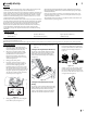

8 Section 2 — ASSembly & Set-Up
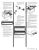
Console Inside
Cover
Figure 2-5
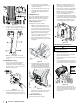
9. Secure the console in place with the six
shoulder screws. See Figure 2-6. Torque the
shoulder screws to 60 in/lbs (+/- 20%).
Figure 2-6
Note: Do not overtighten the shoulder
screws. Doing so can cause damage to the
console.
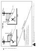
Steering Wheel (If necessary)
1. Remove the hardware for attaching the
steering wheel (a) from beneath the
steering wheel cover (b). Carefully pry off
the steering wheel cover (b) to remove the
hardware. See Figure 2-7.
(d)
(c)
(a)
(b)
(e)
Figure 2-7
2. With the wheels of the tractor pointing
straight forward, place the steering wheel
(a) over the steering shaft (c). See Figure 2-7.
3. Place the belleville washer (d) over the
steering wheel (a) and secure with the hex
screw (e). See Figure 2-7.
4. Place the steering wheel cover (b) over the
center of the steering wheel (a) and push
downward until it “clicks” into place. See
Figure 2-7.
Install Operator’s Seat
There are two shipping methods for the seats,
either the seat pan is attached to the seat or
installed onto the tractor. Proceed with the
instructions for your applicable model.
Seat Pan attached to Seat
To install the seat proceed as follows:
Note: The seat is shipped with the seat
switch and seat pan attached. A second
person may be needed to hold the seat.
1. Cut any straps securing the seat assembly to
the tractor. Remove any packing material.
Note: Be careful not to cut the wiring
harness connecting the seat and the seat
switch in the bottom of the seat.
2. Remove the two shoulder screws (a) and
flange lock nuts (b) in the seat pan as shown
in Figure 2-8.
(a)
(b)
(a)
(b)
Figure 2-8
3. Rotate the seat into position and secure the
seat into place with the previously removed
shoulder screws (a) and flange lock nuts (b).
Be careful not to crimp or damage the wire
harness while installing the seat. See Figure 2-9.
(a)
(b)
(a)
(b)
Figure 2-9
Note: Be sure to push the excess wire from
the wire harness into the seat box hole
before continuing.
Seat Pan attached to Tractor
To install the seat proceed as follows:
Note: The seat is shipped with the seat
switch and seat pan attached. A second
person may be needed to hold the seat.
1. Cut any straps securing the seat assembly to
the tractor. Remove any packing material.
Note: Be careful not to cut the wiring
harness connecting the seat and the seat
switch in the bottom of the seat.
2. Using the four provided bolts (a), install the
seat onto the seat pan. Place the screws (b)on
the front of the seat through the middle hole
in the seat pan (c) as shown in Figure 2-10.
Securely tighten the seat to the seat pan.
Figure 2-10
Lower Deck Discharge Chute Deflector
WARNING
Never operate the mower deck without the chute deflector
installed and in the down position.
Note: For models with a 46”, 50” and 54”
Deck skip ahead to step 6.
1. Remove the keys that are attached with a
zip tie to the chute bracket.
2. Remove the flange lock nut and hex screw
from the deck.
3. Place the chute deflector on the deck, be
sure to insert the tabs on the chute deflector
into the holes on the deck. See Figure 2-11.
3
4
5
5
4
Figure 2-11
4. When the tabs are installed in the deck,
slide the chute deflector toward the rear of
the tractor until the bolt hole in the chute
deflector aligns with the hole in the deck.
See Figure 2-11.