
Full Product Manual

9Section 2 — ASSembly & Set-Up
5. Secure the chute deflector in place with the
flange lock nut and hex screw removed in step
2. Tighten to 102-124 in-lbs. See Figure 2-11.
6. On models with a 46”, 50” and 54” decks
the chute is shipped attached and with a
stop bracket holding the chute upright. The
stop brackets must be removed prior to
operating the tractor.
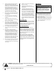
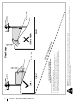
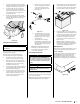
7. Holding the chute deflector fully upward,
remove the shipping brace. Lower the chute
deflector and discard the shipping brace.
See Figure 2-12.
Figure 2-12
Setting the Front Gauge Wheels
WARNING
Keep hands and feet away from the discharge opening of
the cutting deck.
Note: The deck wheels are an anti-scalp feature
of the deck and are not designed to support the
weight of the cutting deck.
Move the tractor on a firm and level surface,
preferably pavement, and proceed as follows:
1. Check the tire pressure, make sure the
pressure is correct and equal on all tires.
2. Make sure the deck is level, both front-to-
back and side-to-side. See the Maintenance
& Adjustments section for deck leveling
information and instructions.
3. Select the height position of the cutting deck
by placing the deck lift lever in the normally
desired mowing height setting.
4. Check the wheels for contact or excessive
clearance with the surface below. The deck
wheels should have between ¼” and ½”
clearance above the ground. Proceed as
follows to adjust the wheels:
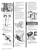
a. Remove the lock nut securing one
of the front gauge wheel shoulder
screws to the deck. Remove the
gauge wheel and shoulder screw.
See Figure 2-13.
(a)
(b)
(c)
Figure 2-13
b. Insert the shoulder screw into the
one of four index holes in the front
gauge wheel bracket that will give
the gauge wheel a ⁄⁄” clearance
with the ground.
c. Note the index hole of the just
adjusted wheel, and adjust the other
front gauge wheel into the respective
index hole of the other front gauge
wheel bracket.
Note: Refer to Adjusting the Deck in the
Product Care section of this manual for
more detailed instructions regarding
various deck adjustments.
Connecting the Battery Cables
WARNING
California
PROPOSITION 65 WARNING: Battery
posts, terminals, and related accessories contain lead and
lead compounds, chemicals known to the State of California
to cause cancer and reproductive harm. Wash hands after
handling.
CAUTION
When attaching battery cables, always connect the
POSITIVE (Red) wire to its terminal first, followed by the
NEGATIVE (Black) wire.
For shipping reasons, both battery cables on your
equipment may have been left disconnected from
the terminals at the factory. To connect the battery
cables, proceed as follows:
Note: The positive battery terminal is marked Pos. (+).
The negative battery terminal is marked Neg. (–).
1. Remove the plastic cover, if present, from the
positive battery terminal and attach the red
cable to the positive battery terminal (+) with
the bolt (a) and hex nut (b). See Figure 2-14.
(b)
(b)
(a)
(a)
(c)
Figure 2-14
2. Remove the plastic cover, if present, from the
negative battery terminal and attach the black
cable to the negative battery terminal (–) with
the bolt (a) and hex nut (b). See Figure 2-14.
3. Position the red rubber boot (c) over the
positive battery terminal to help protect it
from corrosion.
Note: If the battery is put into service after
the date shown on top/side of battery, charge
the battery as instructed in the Product Care
section prior to operating the tractor.
Adjusting the Seat
There are three seat adjustment methods, proceed
with the instructions for your applicable model.
Front Lever Adjust
To adjust the position of the seat, push left and hold
the seat adjustment lever. Slide the seat forward
or rearward to the desired position; then release
the adjustment lever. Make sure seat is locked into
position before operating the tractor. See Figure 2-15.
Figure 2-15