Important Safe Operation Practices • Assembly & Set-Up • Controls & Operation • Product Care Operator’s Manual Lawn Tractor & Garden Tractor Table of Contents Important Safe Operation Practices...................... 2 Product Care............................................................16 Assembly & Set-Up................................................... 7 Parts/Warranty............... See Separate Supplement Controls & Operation..............................................
Important Safe Operation Practices 2 WARNING This symbol points out important safety instructions which, if not followed, could endanger the personal safety and/or property of yourself and others. Read and follow all instructions in this manual before attempting to operate this machine. Failure to comply with these instructions may result in personal injury. When you see this symbol.
Slope Operation 7. Slopes are a major factor related to loss of control and tip-over accidents which can result in severe injury or death. All slopes require extra caution. If you cannot back up the slope or if you feel uneasy on it, do not mow it. For your safety, use the slope gauge included as part of this manual to measure slopes before operating this machine on a sloped or hilly area.
j. k. l. To reduce fire hazards, keep machine free of grass, leaves, or other debris build-up. Follow the “Post-Operation Tractor Care” instructions in the Product Care section. Clean up oil or fuel spillage and remove any fuel soaked debris. Never store the machine or fuel container inside where there is an open flame, spark or pilot light as on a water heater, space heater, furnace, clothes dryer or other gas appliances. Thoroughly inspect the machine for any damage.
Safety Symbols This page depicts and describes safety symbols that may appear on this product. Read, understand, and follow all instructions on the machine before attempting to assemble and operate. Symbol Description READ THE OPERATOR’S MANUAL(S) Read, understand, and follow all instructions in the manual(s) before attempting to assemble and operate DANGER — ROTATING BLADES Never carry passengers. Never carry children, even with the blades off.
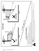
Section 2 — Important Safe Operation Practices Figure 1 line Figure 2 (TOO STEEP) 15°/25% Slope Do not operate machine on slopes in excess of 15 degrees. All slopes require extra caution. If you cannot back up the slope or if you feel uneasy on it, do not mow it. Always mow up and down slopes, never across the face of slopes. WARNING! Slopes are a major factor related to tip-over and roll-over accidents which can result in severe injury or death. To check the slope, proceed as follows: 1.
Assembly & Set-Up 2 Thank You Thank you for purchasing this product. It was carefully engineered to provide excellent performance when properly operated and maintained. Please read this entire manual prior to operating the equipment. It instructs you how to safely and easily set up, operate and maintain your machine. Please be sure that you, and any other persons who will operate the machine, carefully follow the recommended safety practices at all times.
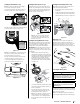
4. Then with the previously removed shoulder bolts (a) and flange lock nuts (b) secure one side of the seat and seat bracket. While supporting the seat, remove the Phillips screwdriver and secure the other side of the seat. Be careful not to crimp or damage the wire harness while installing the seat. See Figure 2-3. Installing the Hood Collar (If necessary) There are three (3) alignment posts (a) on the hood collar (b) that line up with corresponding alignment holes (c) in the hood (d). See Figure 2-6.
Installing the Plenum (If necessary) Installing the Dash Cap (If necessary) Installing the Front Bumper (If necessary) Note: Be careful not to damage the headlight harness when installing the plenum. To install the dash cap (a), line up the tabs (b) on the dash cap (a) with the holes in the upper dash as shown in Figure 2-14. Slide the tabs (b) into the holes in the upper dash and push forward (c) on the dash cap (a) to lock into place.
1. Remove the plastic cover, if present, from the positive battery terminal and attach the red cable to the positive battery terminal (+) with the bolt (a) and hex nut (b). See Figure 2-18. 4. Check the wheels for contact or excessive clearance with the surface below. The deck wheels should have between ¼” and ½” clearance above the ground. Proceed as follows to adjust the wheels: (b) (b) (a) (c) a. Raise the deck lift handle to its highest setting. b.
Controls & Operation Choke Control (If equipped) (E) The choke control is located on the dash panel to the right of the throttle/choke or throttle control and controls the position of the engine choke. Pull the knob out/ up to choke the engine; push the knob in/down to open the choke. (M) (L) (C) (G) (D) (E) (K) (P) (H) 3 (A) (B) (F) (I) Deck Lift Lever (F) Electric PTO tractors (N) (O) Manual PTO tractors (Q) (J) Figure 3-1 Note: This Operator’s Manual covers several models.
PBS (Push Button Start)/Service Minder & Hour Meter w/ Bluetooth® (If equipped) INSERT KEY AND PUSH START / STOP BUTTON (HOUR METER AND LIGHTS COME ON) TO START: DEPRESS BRAKE, PUSH& HOLD START/STOP BUTTON FOR 1.5 SEC. PBS tractors come with TO TURN OFF : PRESS or without Bluetooth®. If equipped, connect your Bluetooth® enabled LCD service minder & hour meter to your smartphone by downloading the App for your Bluetooth® capable Android or iOS device.
Operator’s Manual. Low Oil (If equipped) The letters “LO” followed by the letters “OIL”, then followed by the meter’s accumulated time will indicate the tractor is low on oil. When an engine is not running and immediately after the engine is started the oil pressure may be low. This can trigger the “LO” “OIL” text. This is normal. If the low oil indication persists stop the tractor immediately and check the engine oil level as instructed in the Engine Operator’s Manual.
PBS Ignition 1. Place the PTO in the DISENGAGED (OFF) position. 2. Fully engage the tractor’s brake. 3. Move the throttle into the FAST 4. Insert the ignition key and press the ignition key. position. Note: When operating the tractor be certain that the throttle lever is always in the FAST position. Operating with the throttle at less than full throttle may lead to shortened battery life. Stopping the Engine 3. (c) at Press the REVERSE PUSH BUTTON the top, right corner of the ignition module.
Driving On Slopes Refer to the SLOPE GAUGE on page 6 to help determine slopes where you may operate the tractor safely. WARNING Do not mow on inclines with a slope in excess of 15 degrees (a rise of approximately 2-1⁄2 feet every 10 feet). The tractor could overturn and cause serious injury. • Mow up and down slopes, NEVER across. • Exercise extreme caution when changing direction on slopes. • Watch for holes, ruts, bumps, rocks, or other hidden objects. Uneven terrain could overturn the machine.
4 Product Care Maintenance Schedule Before Each use Check/Clean Engine Intake Screens & Cooling Fans * Check/Clean Exhaust Manifold, Muffler Pipe & Muffler Shields * Check/Clean Hood/Dash Panel Louvers * Check/Clean Top & Underside of Deck, Under and Around Spindle Covers & Belt Area * Check/Clean Around Fuses, Wiring and Wiring Harnesses * Check/Clean Around Transmission, Axle and Fans * Check Engine Oil Level Check Air Filter for Dirty After First 5 Hours Every 10 Hours Every 25 Hours Every 50 Hours
Note: This Operator’s Manual covers several models. Tractor features may vary by model. Not all features in this manual are applicable to all tractor models and the tractor depicted may differ from yours. WARNING Before inspecting or cleaning always disengage the PTO, set the parking brake, stop the engine and remove the key to prevent unintended starting. 8. Remain in the operator’s position with the deck engaged for a minimum of two minutes, allowing the underside of the deck to thoroughly rinse. 9.
Maintenance Charging Run the engine for a short time to warm the engine oil. The oil will flow more freely and carry away more impurities. Use care to avoid burns from hot oil. 2. Open the tractor’s hood and locate the oil drain port on the side of the engine. 3. Place an appropriate oil collection container with at least a 2.5 quart capacity below the opening of the oil drain tube, to collect the used oil. Remove the oil fill cap/dipstick from the oil fill tube. 4.
Lubrication ydrostatic Transmission DANGER Bearing failures and overheating can result in fire/ Always follow the instructions in this manual regarding lubrications locations and intervals. Contact your authorized dealer with any questions about the lubrication locations and intervals or any unusual noises coming from any areas a bearing may be located.
The deck wheels should be approximately 1⁄4-1⁄2” above the ground when the deck is set in the desired height setting. To adjust the deck wheels see the Assembly & Set-Up section for instructions. 4. Refer to the Assembly & Set-Up section of this manual for seat adjustment instructions. Before operating the tractor, make sure the seat is engaged in the seat-stop. Engage the parking brake. Stand behind the machine and pull back on seat until it clicks into place.
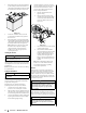
9. Pivot the wrench forward to move the deck drive pulley forward. See Figure 4-3. WARNING Avoid pinching injuries. Never place your fingers on the idler spring or between the belt and a pulley while installing the belt. 10. Carefully remove the belt from around the PTO pulley. 11. Looking at the deck from the left side of the tractor, locate the bow-tie pin on the rear left side of the deck. See Figure 4-4. Cutting Blades 5.
5. 6. 46” Decks 7. 8. 9. Retighten idler pulleys, if loosened earlier. Remount the spindle covers if removed earlier. Re-install the deck make sure the belt remains routed around the pulleys as instructed. On manual PTO units, re-install the engine pulley keeper rod and the PTO cable. Pull the right side of the belt and place the narrow V side of the belt into the PTO pulley. See Figure 4-11.