ST23 ST26 ST35 Trimmers Operator's Manual
TABLE OF CONTENTS Table of Contents .............................................. 1 Foreword ........................................................... 1 Safety Precautions ............................................ 2 Metal Blade Use ................................................ 6 Decal Information .............................................. 7 Specifications .................................................... 8 Parts Description ............................................... 9 Trimmer Assembly .
SAFETY PRECAUTIONS GENERAL: regular users should monitor closely the condition of their hands and fingers. If any of the above symptoms appear, seek medical advice immediately. 1. It is important that you read, fully understand and observe the following safety precautions and warnings. Read the Operator's Manual and the safety instructions periodically. PROTECTIVE CLOTHING: Trimmer operation can cause serious injury to eyes, ears and body.
SAFETY PRECAUTIONS 2. Spectators, children, fellow workers and animals must be warned to stay back 50 feet (15m) while the trimmer is in use. Stop the engine and cutting head immediately if you are approached. fuel. 3. Fuel your trimmer outdoors or in a well-ventilated area. 3. People working in the area near you should wear the same protective equipment as the operator. 4. Select bare ground for fueling and move at least 10 feet (3 m) from the fueling spot before starting the engine.
SAFETY PRECAUTIONS STARTING: Your trimmer is a one-person machine. 8. Before trimming, inspect the area for stones, glass, pieces of metal, trash or other solid objects. The cutting line could throw objects of this kind. 1. Start and operate your trimmer without assistance. When starting, place the trimmer on firm ground or a solid surface in an open area. Maintain good balance and secure footing. 9.
SAFETY PRECAUTIONS immediately. The retaining bolt may be worn or damaged and should be replaced. Never use unauthorized parts to secure the blade. If the blade continues to loosen, see your Cub Cadet Commercial dealer. Never use a trimmer with a loose blade. 16. To reduce the risk of personal injury from loss of control, do not use an incorrect idle adjustment. At correct idle speed, the head and line or blade should not move.
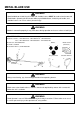
METAL BLADE USE WARNING Specified deflector shield, bicycle handle and shoulder harness MUST be used on brushcutter with metal blades. Operating the brushcutter without specified deflector, shield, bicycle handle, and shoulder harness can cause serious personal injury. WARNING If blade is mounted improperly, it may come loose during operation and cause serious or fatal injury. REQUIRED PARTS………………Parts List on 3,4 page A. Blades; 23,26cc; 1.IM-195833140 2.IM-195833170 3.IM-195833230 35cc; 1.
DECAL INFORMATION WARNING LOCATE THE SAFETY DECALS ON YOUR TRIMMER. MAKE SURE THE DECALS ARE LEGIBLE AND THAT YOU UNDERSTAND AND FOLLOW THE INSTRUCTIONS ON THEM. DEFLECTOR DECAL: SHAFT DECALS: (Continued) KICKOUT Beware of KICKOUT (blade thrust) when using blades. Special precautions are necessary for blade operation, see your Operator's Manual.
SPECIFICATIONS Model Length Width Height Weight ST23 Loop Handle ST26 Loop Handle ST35 Loop Handle (mm) 1783 1783 1818 (in.) 70.1 70.1 71.5 (mm) 260 260 260 (in.) 10.2 10.2 10.2 (mm) 250 264 277 (in.) 9.84 10.4 10.9 (kg) 4.8 5.1 6.7 (lb.) 10.5 11.2 14.7 Type of Engine Bore Stroke Displacement Engine Power Air-cooled, two-stroke, single cylinder gasoline engine. (mm) 33 33 37 (in.) 1.3 1.3 1.46 (mm) 26 30 32 (in.) 1.02 1.18 1.26 (cc) 22.2 25.
PARTS DESCRIPTION WARNING • Prevent accidental contact with unit and any cuting attachment. Maintain a 50 ft. (15 m) radius, DANGER ZONE surrounding the operator. ONLY the operator, dressed in proper protective clothing should be in the DANGER ZONE. • Beware of KICKOUT【blade thrust】when using blades. Special precautions are necessary for blade operation, see your Operator and Safety Manual.
TRIMMER ASSEMBLY The trimmer is partly disassembled for ease of shipment and must be assembled before it can be used for the first time. 6. Line up the loop handle and tighten the screws firmly. B. MOUNTING THE DEFLECTOR: WARNING 1. To mount the deflector, lay the trimmer on its back with the cutting tool head facing upward. Because of the increased risk of accidents the powerhead must not be started while it is detached from the trimmer. 2 A. MOUNTING THE LOOP HANDLE: 1 1 (A) ( B) 2.
TRIMMER ASSEMBLY D. USING THE SHOULDER HARNESS (Standard on ST35): WARNING If the nylon line trimmer head or the blade is fitted improperly, it may come loose during operation and cause serious or fatal injury. 1 Installing the Nylon Line Trimmer Head 4 1. Put on the shoulder strap (Ref. 1). WARNING Always use the shoulder harness when using rigid blades. 2 3 Installing steel blade 7 6 5 4 1 3 2 WARNING Protect your hands with gloves if mounting a rigid blade. 1 2.
FUELING INSTRUCTIONS 6. Install the bolt cover (Ref.6). 7. Install the left hand nut (Ref.7) tighten to 18.5 (N • m). 2. Add the proper amount of two-stroke oil and mix thoroughly. 3. Add the remainder of the gasoline and mix thoroughly. WARNING Take care when handling gasoline. Avoid direct contact with the skin and avoid inhaling fuel vapor. Reread the Safety Precautions relating to “Handling Fuel” on Page 3.
FUELING INSTRUCTIONS FUEL MIXTURE : When using Cub Cadet Commercial 50:1 2-cycle brand oil, or a quality oil designed for 2-cycle aircooled engines, oil ratio is 50 parts gasoline to 1 part oil or 50:1. Always use a spoul or funnel when fueling to reduce fuel spillage. Only fill the tank to within 1/41/2 inch from the top of the tank. Avoid filling to the top of the tank filler neck. CAUTION Never use a mixing ratio greater than 50:1 regardless of the oil package mixing instructions.
OPERATION A. STARTING: WARNING 3 Reread the Safety Precautions relating to “Starting” on Page 3. WARNING When the engine starts, the cutting tool may rotate even with the throttle trigger in the low-speed position possibly causing injury. 1. When the Engine is Cold. STOP c. Close the choke (Ref.3) completely. 1 START 5 4 d. Grasp the throttle trigger (Ref.4) fully, then release it slowly while pushing the lock button (Ref.5). This sets the throttle trigger at halfthrottle. a.
OPERATION e. Put the unit on the ground: It must rest securely on the engine support and deflector. Check that the cutting tool is not touching the ground or any other obstacles. 7 f. Make sure you have a firm footing: Hold the unit with your left hand and press it down firmly. Do not stand or kneel on the drive shaft. g. Pull the starter grip: When pulling the starting rope (Ref. 6), use short pulls, 1/2 to 2/3 of the rope length.
OPERATION B. STOPPING: STOP 1 START 1. Return the throttle to the “IDLE” position and let the engine run for 2 or 3 minutes until it has cooled down. 2. Slide the ignition switch (Ref.1) to the “STOP” position. WARNING Reread the Safety Precautions relating to “Operation” on Page 4.
MAINTENANCE NOTE: MAINTENANCE, REPLACEMENT, OR REPAIRE OF THE EMISSION CONTROL DEVICE AND SYSTEMS MAY BE PERFORMED BY ANY NONROAD ENGINE REPAIRE ESTABLISHMENT OR INDIVIDUAL.
MAINTENANCE EMISSION PARTS MAINTENANCE CHART PART MAINTENANCE Air Filter Clean Element Replace Spark Plug Check / Clean / Adjust BEFORE MONTHLY or THREE MONTHS or SIX MONTHS or YEARLY or 50 HOURS USE 150 HOURS USE 300 HOURS USE 600 HOURS USE USE X 21 X X Replace Carburetor SEE PAGE 20 X Clean (*1) X Overhaul (*2) / Replace (*3) 18,19 X (*1) • At an authorized Cub Cadet Commercial servicing facility to be charged.
MAINTENANCE 6. Adjusting the idle speed: It is usually necessary to change the setting of the idle speed adjusting screw (Ref. I) after every correction to the low speed adjusting screw (Ref. L). 7. Proper idling speed: ST23,26............. 2,800-3,000 rpm ST35.................. 2,500-2,700 rpm 8. The engine stops while idling: Turn the idle speed adjusting screw (Ref. I) clockwise until the engine runs smoothly, but the cutting tool must not rotate. 9.
MAINTENANCE B. THE THROTTLE WIRE ADJUSTMENT C. CHECKING THE SPARK PLUG. A 0.5mm-0.6mm 0.020”-0.024” The wrong fuel mix (too much engine oil in the gasoline), a dirty air filter or unfavorable running conditions (mostly at low throttle) affect the condition of the spark plug. These factors cause deposits to form on the insulator nose which may result in faulty operation. 1. If the engine doesn't seem to have any power, is difficult to start or runs poorly at idling speed, first check the spark plug.
MAINTENANCE D. CLEANING THE AIR FILTER. Dirty air filters reduce engine power, increase fuel consumption and make starting more difficult. If there is a noticeable loss of engine power: ST23, 26 ST35 1 3 5 4 5 4 1. Turn the choke lever (Ref. 1) to “CLOSE”. Loosen the screw (Ref. 2) and remove the air filter cover (Ref. 3). 3 IMPORTANT To maintain proper engine operating temperatures, cooling air must pass freely through the cylinder fin area.
MAINTENANCE 2. Dust and grass build up on the outside of the cylinder. This buildup insulates the engine and prevents the heat from leaving. 2. Place the piston at top dead center. Clean any deposits from the muffler and the cylinder exhaust port with a nonmetallic scraper. Removal of cooling passage blockages or cleaning of cylinder fins is considered “Normal Maintenance”. Any resultant failure attributed to lack of maintenance is not warranted.
MAINTENANCE 1. Remove the filler plug. I. FUEL SYSTEM. 2. Check the level and add grease, if necessary, using a pressure pump. Leave about 5-10 g (1/4 oz.) for any expansion of grease. NOTE: Use a good quality lithium multipurpose grease. DO NOT overfill the housing. 3. Tighten the filler plug firmly. K. LUBRICATING THE DRIVE SHAFT. Shaft 1. Change the fuel pick up body every year. 2.
TROUBLESHOOTING GUIDE PROBLEM CAUSE SOLUTION No Fuel at Carburetor Fuel Filter Dirty Fuel Line Clogged Carburetor Replace Clean See your Cub Cadet dealer No Fuel at Cylinder Carburetor See your Cub Cadet dealer Muffler Wet with Fuel Fuel Mixture is too Rich Open Choke Clean/Replace Air Filter Adjust Carburetor See your Cub Cadet dealer No Spark at Plug End of Wire Ignition Switch Off Electrical Problem Turn Switch On See your Cub Cadet dealer No Spark at Spark Plug Spark Gap Incorrect Covere
MANUFACTURER’S LIMITED WARRANTY FOR: Cub Cadet Corporation's limited warranty promises to you, the original retail purchaser, that the unit of Cub Cadet Commercial hand held power equipment you purchased (the "Product") will be free from defects in material and workmanship for, as applicable: a period of one (1) year from the date of retail purchase for commercial purchasers and/or users, and a period of two (2) years from the date of retail purchase for residential purchasers and/or users (the "Warranty p
U. S. EPA EMISSION CONTROL WARRANTY STATEMENT YOUR WARRANTY RIGHTS AND OBLIGATIONS The U.S. Environmental Protection Agency (EPA), Cub Cadet Corporation and the engine manufacturer for this equipment, Ishikawajima Shibaura Machinery Co., Ltd. (ISM), are pleased to explain the federal emission control systems warranty on your engine. In the U. S.
WARRANTY STATEMENT (continued) Any warranted part which is scheduled for replacement as required maintenance is warranted for the period of time up to the point of first scheduled replacement. A replacement part installed prior to the first scheduled replacement due to a defect in the original part shall be warranted until the date of the first scheduled replacement. The owner is responsible for the performance of all required maintenance listed in the Operator’s Manual.
ST23 ST26 ST35 Trimmers Parts List
ENGINE, ST23 TRIMMER 48 37 41 50 38 49 47 34 33 36 21 22 52 43 58 27 31 33 44 26 46 30 6 32 53 3 2 5 10 1 12 62 61 54 6 7 56 57 14 91 15 19 13 1 13 9 90 11 8 66 88 89 10 16 33 81 87 68 59 67 69 72 47 65 82 80 79 63 64 45 55 4 70 35 51 23 29 35 42 25 28 40 24 20 78 76 77 75 74 83 18 17 73 84 71 85 35
ENGINE, ST23 TRIMMER – PARTS LIST Ref. Parts No. No. Description No. Used 2 1 IM-115253421 Crankshaft ........................ 1 2 IM-034309031 Key ................................... 1 3 IM-115013300 Piston Assembly (Includes 2 Ref. 4) ............................ 1 4 IM-115113650 Ring, Piston ...................... 2 5 IM-115323130 Pin, Piston ........................ 1 6 IM-198343210 Clip, Piston Pin ................. 2 7 IM-042709007 Bearing, Needle ................
SHAFT, ST23 TRIMMER 32 14 Optional 28 35 31 10 33 30 16 29 2 15 36 47 3 37 48 20 3 17 18 19 20 49 7 58 8 50 4 21 22 23 41 5 38 40 39 1 24 54 25 55 26 11 27 56 53 6 51 57 12 9 10 13 52
SHAFT, ST23 TRIMMER – PARTS LIST Ref. Parts No. No. Description No. Used 4 1 IM-720113160 Shaft, Drive ....................... 1 2 IM-720124320 Pipe, Complete (Includes 6 Ref. 3) ............................ 1 3 IM-720133160 Metal ................................. 6 4 IM-720203082 Hanger .............................. 1 5 IM-720973178 Bolt, M6x14 ....................... 1 6 IM-720623400 Grip ................................... 1 7 IM-125034130 Lever Assembly, Throttle (Includes 1 Ref. 8) ............
ENGINE, ST26 TRIMMER 35 33 30 65 27 43 42 44 41 34 31 19 20 25 26 21 24 32 36 22 23 28 29 56 55 54 81 12 12 5 45 51 47 38 3 37 1 2 46 50 82 48 4 9 6 52 13 86 14 11 49 8 57 58 53 85 75 1 8 76 60 71 84 73 15 7 16 18 9 74 77 70 69 67 83 10 72 59 28 68 26 62 61 17 63 78 64 66 79 39
ENGINE, ST26 TRIMMER – PARTS LIST Ref. Parts No. No. Description No. Used 2 1 IM-115253470 Crankshaft ........................ 1 2 IM-115013311 Piston Assembly (Includes 2 Ref. 3) ............................ 1 3 IM-115113650 Ring, Piston ...................... 2 4 IM-115323040 Pin, Piston ........................ 1 5 IM-198343210 Clip, Piston Pin ................. 2 6 IM-042709008 Bearing, Needle ................ 1 7 IM-110035190 Crankcase Assembly (Includes 1 ea. Ref. 8,9 and 2 ea. Ref. 10) ..........
SHAFT, ST26 TRIMMER 32 14 Optional 28 35 31 10 33 30 16 29 36 2 15 43 3 44 20 3 45 37 17 18 19 20 7 54 8 46 4 21 22 23 5 1 24 50 25 51 26 11 27 52 49 6 47 53 12 9 10 13 48
SHAFT, ST26 TRIMMER – PARTS LIST Ref. Parts No. No. Description No. Used 4 1 IM-720113160 Shaft, Drive ....................... 1 2 IM-720124330 Pipe, Complete (Includes 6 Ref. 3) ............................ 1 3 IM-720133160 Metal ................................. 6 4 IM-720203082 Hanger .............................. 1 5 IM-720973178 Bolt, M6x14 ....................... 1 6 IM-720623400 Grip ................................... 1 7 IM-125034130 Lever Assembly, Throttle (Includes 1 Ref. 8) ............
ENGINE, ST35 TRIMMER 1 102 98 96 97
ENGINE, ST35 TRIMMER – PARTS LIST Ref. Parts No. No. Description No. Used 2 1 IM-115253440 Crankshaft ........................ 1 2 IM-034309031 Key ................................... 1 3 IM-115013280 Piston Assembly (Includes 2 Ref. 4) ............................ 1 4 IM-115113730 Ring, Piston ...................... 2 5 IM-115323030 Pin, Piston ........................ 1 6 IM-198343040 Clip, Piston Pin ................. 2 7 IM-042709006 Bearing, Needle ................
SHAFT, ST35 TRIMMER Optional 3 51 52 53 50 48 49
SHAFT, ST35 TRIMMER – PARTS LIST Ref. Parts No. No. Description No. Used 4 1 IM-720113120 Shaft, Drive ....................... 1 2 IM-720124290 Pipe, Complete (Includes 6 Ref. 3) ............................... 1 3 IM-720133061 Metal ................................. 6 4 IM-720203073 Hanger .............................. 1 5 IM-720973178 Bolt, M6x14 ....................... 1 6 IM-720623251 Grip ................................... 1 7 IM-125034150 Lever Assembly, Throttle (Includes 1 Ref. 40) ..........
100814820. M2,5. F9. Sh. Printed in Japan.