Safety • Assembly • Operation • Maintenance • Troubleshooting • Parts Lists • Warranty OPERATOR’S MANUAL Yard Vacuum/Chipper/Shredder with Vacuum/Hose Model Series 060 IMPORTANT READ SAFETY RULES AND INSTRUCTIONS CAREFULLY BEFORE OPERATION Warning: This unit is equipped with an internal combustion engine and should not be used on or near any unimproved forest-covered, brushcovered or grass-covered land unless the engine’s exhaust system is equipped with a spark arrester meeting applicable local or state l
This Operator’s Manual is an important part of your new chipper shredder vacuum. It will help you assemble, prepare and maintain the unit for best performance. Please read and understand what it says. Table of Contents Customer Support............................................... 2 Safety Labels....................................................... 3 Safe Operation Practices.................................... 4 Setting Up Your Chipper Shredder Vacuum...... 6 Operating Your Chipper Shredder Vacuum......
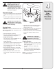
Safety Labels Found On Your Chipper Shredder Vacuum 1 Safety Labels DANGER TO AVOID SERIOUS INJURY • READ OPERATOR'S MANUAL. • KEEP HANDS OUT OF INLET AND DISCHARGE OPENINGS WHILE MACHINE IS RUNNING. ROTATING BLADES ARE INSIDE. • TURN ENGINE OFF AND ALLOW IMPELLER TO COME TO COMPLETE STOP BEFORE REMOVING BAG. • DO NOT ATTEMPT TO CLEAR A CLOG OR JAMWITH THE ENGINE RUNNING. • DO NOT OPERATE UNIT WITHOUT BAG OR OPTIONAL BLOWER CHUTE IN PLACE.
2 Safe Operation Practices WARNING This symbol points out important safety instructions which, if not followed, could endanger the personal safety and/or property of yourself and others. Read and follow all instructions in this manual before attempting to operate this machine. Failure to comply with these instructions may result in personal injury. When you see this symbol.
Operation Maintenance & Storage 1. Do not put hands and feet near rotating parts or in the feeding chambers and discharge opening. Contact with the rotating impeller can amputate fingers, hands, and feet. 2. Before starting the machine, make sure the chipper chute, feed intake, and cutting chamber are empty and free of all debris. 3.
3 IMPORTANT: This unit is shipped without gasoline or oil in the engine. Be certain to service engine with gasoline and oil as instructed in the separate engine manual before operating your machine. Loose Parts In Carton a. Upper and Lower Handle Setting Up Your Chipper Shredder Vacuum b. Hose Assembly c. Safety Glasses B d. Engine Oil (May be located in bag) e. Bag NOTE: All references in this manual to the left or right side of the chipper shredder vacuum is from the operating position only.
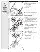
3 Attaching The Hose Assembly 5. a. Slide hose adapter of hose assembly into the base adapter located on the left front of the Chipper shredder Vacuum. See Figure 3-4. b. Pull spring loaded pin out on the base and align pin with the first hole (closest to the end of the tube) in the hose adapter. c. Release the pin to lock the hose in place. 6. a. Snap the hose handle first into the upper hose handle bracket and then into the lower hose handle bracket. See Figure 3-5. b.
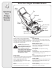
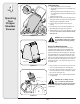
4 Know Your Chipper Shredder Vacuum Starter Handle Bag Operating Your Chipper Shredder Vacuum Bag Handle Oil Fill Gasoline Fill Hose Handle Hose Assembly Chipper Chute Nozzle/Hose Vac Lever Nozzle Nozzle Height Adjustment Lever Figure 4-1 Hose Assembly Now that you have set up your chipper shredder Used as an alternative to the nozzle to vacuum yard vacuum for operation, get aquainted with its controls and features.
WARNING: Use extreme care when handling gasoline. Gasoline is extremely flammable and the vapors are explosive. Never fuel machine indoors or while the engine is hot or running. Extinguish cigarettes, cigars, pipes, and other sources of ignition. Throttle Control Choke Control Gas and Oil Fill-Up 1. Check oil level and add oil if necessary. Follow engine manual for this. See Figure 4-1 for location of the oil fill. 2. Service the engine with gasoline as instructed in the engine manual.
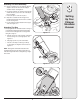
4 Operating Your Chipper Shredder Vacuum To Empty Bag B D 1. a. Unhook bag straps from the lower handle. b. Unsnap bag clip from the top of lower handle. See Figure 4-3. c. Grasp bag handle with one hand and pull lock rod on mounting bracket with other hand toward engine to release. d. Lift bag off back of unit. 2. Twist the two buttons on the back of the bag to unlock and empty contents. See Figure 4-4. Hold bag handle and bag clip while emptying the contents. 3.
4 IMPORTANT: The flail screen is located inside the housing in the discharge area. If the flail screen becomes clogged, remove and clean as instructed in MAINTAINING YOUR Chipper shredder VACUUM. For best performance, it is also important to keep the chipper blade sharp. Using The Hose Assembly 1. Place nozzle/hose vac lever in the bottom position on the nozzle to redirect vacuum to the hose assembly. See Figure 4-6. 2.
5 Maintaining Your Chipper Shredder Vacuum WARNING: Always stop engine, disconnect spark plug, and ground against engine before cleaning, lubricating or doing any kind of maintenance on your machine. Lubrication • • General Recommendations • • • • Always observe safety rules when performing any maintenance. The warranty on this chipper/shredder vacuum does not cover items that have been subjected to operator abuse or negligence.
WARNING: Before performing any type of maintenance on the machine, wait for all parts to stop moving and disconnect the spark plug wire. Failure to follow this instruction could result in personal injury or property damage. 5 Removing the Flail Screen If the discharge area becomes clogged, remove the flail screen and clean area as follows: 1. Stop the engine. Make certain the chipper/shredder vacuum has come to a complete stop. 2.
Sharpening or Replacing Chipper Blade 5 NOTE: When tipping the unit, empty the oil and fuel tank and keep engine spark plug side up. 1. Maintaining Your Chipper Shredder Vacuum 2. 3. 4. 5. Figure 5-3 6. Front Support Brace and Lock Nut Pivot Arm Assembly Bell Washer Thrust Washer Shoulder Screw Wave Washer Lock Nut Wheel Figure 5-4 Figure 5-5 14 Disconnect and ground the spark plug wire to retaining post. Remove bag assembly or blower chute.
7. Carefully tilt and support the unit up to provide access underneath to the nozzle mounting hardware and impeller. Remove the three shoulder bolts securing the black plastic lower flail housing to the lower housing. Refer to Figure 5-6. 8. Tilt top of black plastic lower flail housing toward the engine to remove. 9. Using a 3/16” allen wrench, remove the flat head cap screws that hold the chipper blade to the impeller.
6 Problem Engine fails to start Trouble Shooting Cause 1. Throttle lever not in correct starting position. 1. Move throttle lever to FAST or START position. 2. Spark plug wire disconnected. 2. Connect wire to spark plug. 3. Choke not in CHOKE position (if equipped). 3. Move choke lever to CHOKE position. 4. Fuel tank empty or stale fuel. 4. Fill tank with clean, fresh gasoline. 5. Engine not primed (if equipped). 5. Prime engine as instructed in Engine Manual. 6. Faulty spark plug. 6.
NOTES Use this page to make notes and write down important information.
Model Series 060 2 6 3 34 8 9 5 11 34 23 10 7 22 A 12 17 36 50 14 4 13 7 15 27 25 26 33 A 40 21 37 39 44 42 52 46 41 28 45 29 48 50 51 50 43 40 30 16 38 24 20 18 1 47 49 31 32 18 35 19
Part No. Description Ref. No. Part No. 1. 736-0314 Thrust Washer.375 ID x.70 OD 28. 723-0295 Adjustment Clamp 2. 749-04172 Upper Handle 29. 749-1270 Nozzle Handle 3. 720-0279 Knob 30. 764-0648 Vacuum Hose 4. 710-0599 Screw, 1/4-20 x.500 31. 07071 Handle Grip 5. 710-1205 Eye Bolt 32. 731-2292 Hose Adapter 6. 781-1056 Upper Handle Bracket 33. 712-0442 Cap Lock Nut, 1/4-20 7. 710-0726 Hex Cap Screw 5/16-12 x.750 34. 710-1611B TT Screw, 5/16-18 x .750 8.
Model Series 060 34 37 35 36 1 38 30 39 40 42 41 43 44 48 44 30 46 28 44 29 B 47 49 45 11 2 3 4 15 11 * 10 9 7 8 32 B 13 5 31 33 16 18 19 6 22 23 A A 24 14 12 25 26 21 20 27 20 17
Part No. 1. 681-0180A 2. Description Part No. Bag Assembly 26. 732-1151A Nozzle Door Torsion Spring 681-0154 Screen Assembly 27. 731-2294A Nozzle Door 3. 710-1054 Hex Screw 5/16-24 x 1.0 28. 664-04040 Bag 4. 781-0490 Chipper Blade 29. 631-0083 Chute Assembly 5. 781-0735 Pin Clip 30. 710-0726 Hex Index Screw, 5/16-12 x.750 6. 719-0329 Flail 31. 736-0247 Flat Washer.375 ID x 1.25 OD 7. 715-0166 Spiral Pin 32. 736-0217 Lock Washer 3/8 8. 711-1401 Clevis Pin 33.
CUB CADET LLC MANUFACTURER’S LIMITED WARRANTY FOR Chipper-shredders & Chipper-shredder VACUUMs The limited warranty set forth below is given by Cub Cadet LLC with respect to new merchandise purchased and used in the United States, its possessions and territories, and by MTD Products Limited with respect to new merchandise purchased and used in Canada and/or its territories and possessions. d.
Seguridad•Ensamblaje•Operación•Consejos y Técnicas•Mantenimiento•Solución de problemas•Lista de Parte•Grantías MANUAL DEL OPERADOR Aspiradora Para Patios - Modelo Serie 060 IMPORTANTE LEA CON ATENCIÓN LAS REGLAS DE SEGURIDAD E INSTRUCCIONES ANTES DE OPERAR LA ASPIRADORA PARA PATIOS ADVERTENCIA: Esta unidad está equipada con un motor de combustión interna y no debe ser utilizada en o cerca de un terreno agreste cubierto por bosque, malezas o hierba excepto que el sistema de escape del motor est
Este manual de operador es una parte importante de su nueva aspiradora para patios. Le ayudará a montar, preparar y mantener la unidad para obtener los mejores resultados. Por favor lea y comprenda el contenido del manual. Índice Etiquetas de seguridad..................................... 25 Prácticas de seguridad en la operación.......... 26 Configuración de la aspiradora para patios... 28 Funcionamiento de la aspiradora para patios30 Mantenimiento de la aspiradora para patios.. 34 Solución de problemas.
Etiquetas de Seguridad Encontradas En Su Aspiradora Para Patios DANGER TO AVOID SERIOUS INJURY • READ OPERATOR'S MANUAL. • KEEP HANDS OUT OF INLET AND DISCHARGE OPENINGS WHILE MACHINE IS RUNNING. ROTATING BLADES ARE INSIDE. • TURN ENGINE OFF AND ALLOW IMPELLER TO COME TO COMPLETE STOP BEFORE REMOVING BAG. • DO NOT ATTEMPT TO CLEAR A CLOG OR JAMWITH THE ENGINE RUNNING. • DO NOT OPERATE UNIT WITHOUT BAG OR OPTIONAL BLOWER CHUTE IN PLACE.
2 Prácticas de seguridad en la operación ADVERTENCIA Este símbolo indica instrucciones de seguridad importantes que de no seguirse, se podría poner en peligro la seguridad personal y/o la propiedad suya y de terceros. Lea y siga todas las instrucciones en este manual antes de iniciar la operación de esta máquina. En caso de no seguir estas instrucciones podría provocar lesiones personales.
Operación 1. No ponga las manos o los pies cerca de las piezas rotatorias o en las cámaras de alimentación ni en la abertura de descarga. El contacto con el motor rotatorio puede producir la amputación de dedos, manos o pies. 2. Antes de encender la máquina compruebe que el canal de la cortadora, la toma de alimentación y la cámara de corte están vacías y sin desechos. 3.
IMPORTANTE: Esta unidad se envía sin gasolina ni aceite en el motor. Antes de operar la máquina cargue el motor con gasolina y aceite como se indica en el manual separado del mismo.
Instalación Del Montaje de la Manguera 5. 6. a. Deslice el adaptador para manguera del montaje de la misma hacia el interior del adaptador base ubicado a la izquierda y al frente de la aspiradora para patios. Vea la figura 3-4. b. Tire del perno con resorte del lado exterior de la base, y ponga el perno en línea con el primer agujero (el más cercano al extremo del tubo) del adaptador para manguera. c. Suelte el perno para ajustar la manguera en su lugar. a.
4 Funcionamiento de la Aspiradora Para Patios Conozca las Propiedades de la Aspiradora Para Patios Manija del arrancador Bolsa Manija de la bolsa Llenado de aceite Llenado de combustible Montaje de la manguera Manija de la manguera Palanca del pico / manguera de la aspiradora Canal de la cortadora Palanca Palanca de ajuste de la altura del pico Figura 4-1 Manija de la bolsa Se utiliza para tomar la bolsa para colocarla, sacarla y vaciarla. Vea la figura 4-1.
Mandos de Motor Ver el manual de motor separado para la posición y la función de los mandos en el motor. Control del estrangulador ADVERTENCIA: Tenga extremo cuidado cuando manipule la gasolina. La gasolina es altamente inflamable y los vapores son explosivos. Nunca le agregue combustible a la máquina en interiores o mientras el motor está caliente o en funcionamiento. Apague los cigarrillos, cigarros, pipas y otras fuentes de combustión.
Descarga de la Bolsa 4 B Funcionamiento de la Aspiradora Para Patios D C 1. a. Desenganche las tiras de la bolsa de la manija inferior. b. Suelte el broche de la bolsa a presión de la parte superior de la manija inferior. Vea la figura 4-3. c. Tome la manija de la bolsa con una mano y tire de la varilla de seguridad del soporte de montaje hacia el motor con la otra mano para soltarla. d. Eleve la bolsa fuera de la parte posterior de la unidad. 2.
IMPORTANTE: La pantalla de desgranado está ubicada dentro de la caja en la zona de descarga. Si se tapa la pantalla de desgranado, sáquela y límpiela como se indica en la sección de mantenimiento. Para obtener el mejor resultado es importante también mantener afilada la hoja de la cortadora. 4 Uso Del Montaje De La Manguera 1. Coloque la manija del pico / manguera de la aspiradora en la posición de la base del pico para volver a dirigir la aspiración al montaje de la manguera. Vea la figura 4-6. 2.
5 Mantenimiento de la Aspiradora Para Patios ADVERTENCIA: Detenga siempre el motor, desconecte la bujía y haga masa contra el motor antes de limpiar, lubricar o de realizar todo tipo de mantenimiento de la máquina. Lubricaciòn Recomendaciones Generales • • • • • • Respete siempre las reglas de seguridad cuando realice tareas de mantenimiento. La garantía de esta aspiradora para patios no cubre elementos que han estado sujetos al mal uso o negligencia del operador.
ADVERTENCIA: Antes de realizar cualquier tipo del mantenimiento en la máquina, espere todas las partes a dejar de moverse y desconectar el alambre de bujía. El fracaso de seguir esta instrucción podría causar la herida personal o el daño a la propiedad. 5 Extracciòn de la Pantalla de Desgranado Si la zona de descarga se tapa, saque la pantalla de desgranado y limpie la zona como se indica a continuación. 1. Detenga el motor.
Afilado o Reemplazo de Las Hojas de la Cortadora 5 NOTA: Cuando incline la unidad, vacíe el depósito de combustible y aceite, y mantenga el lado de la bujía hacia arriba. 1. Mantenimiento de la Aspiradora Para Patios 2. 3. 4. Figura 5-3 5. Traba de sostén delantera y tuerca de seguridad Montaje del brazo giratorio Arandela de campana Arandela de arrastre Tornillo con reborde 6.
7. Incline la unidad con cuidado y apóyela hacia arriba para obtener acceso por la parte inferior al material de montaje del pico y al motor. Retire los tres tornillos con reborde que aseguran el pico de plástico negro a la caja inferior. Consulte la figura 5-6. 8. Incline la parte superior del pico de plástico negro hacia el motor para retirarlo. 9. Mediante una llave Allen de 3/16”, retire los tornillos de cabeza plana que sujetan la hoja de la cortadora al motor.
6 Problema El motor no arranca Solución de problemas Si debe realizar reparaciones más importantes que las enunciadas aquí, comuníquese con el distribuidor local autorizado. Causa 1. La palanca del regulador no está en la posición de arranque correcta. 1. 2. La palanca de obturación no está en la posición ON (encendido). Se ha desconectado el cable de la bujía. La bujía no funciona correctamente. El tanque de combustible está vacío o el combustible es viejo. 2. 6.
Problema Funciona mal en marcha lenta Demasiada vibración La unidad no descarga La tasa de descarga se reduce de manera considerable o cambia la composición del material descargado Causa Remedio 2. Carburador ajustado incorrectamente. 1. Sustituya la bujía y ajuste el hueco. 2. Consulte el manual del motor. 3. El filtro de aire está sucio. 3. Consulte el manual del motor. 1. Hay partes que están flojas o el motor está dañado. 1. Detenga el motor de inmediato y desconecte el cable de la bujía.
GARANTÍA LIMITADA DE CUB CADET LLC PARA cortadoras trituradoras y aspiradoras para cortadoras trituradoras La siguiente garantía limitada es otorgada por Cub Cadet LLC con respecto a nuevos productos adquiridos y utilizados en Estados Unidos, sus posesiones territorios, y por MTD Products Limited con respecto a nuevos productos adquiridos y utilizados en Canadá y/o sus territorios y posesiones. d.