
user manual


PROPER GRIP ON HANDLE
• Always maintain a proper grip on the handles whenever the motor is running.
Grip the unit firmly with both hands. Keep the left hand on the D-handle and
the right hand on the shaft grip. The fingers should encircle the handle(s) and
the thumb(s) should wrap under the handle(s). The left arm should be straight
and the right arm slightly bent.
PROPER STANCE
• Balance body weight securely, with both feet on solid ground.
WORK AREA PRECAUTIONS
• Keep everyone – helpers, bystanders, children and animals – at least 50 feet
(15 m) away from the work area. If anyone enters the work area, stop the unit!
• Only operate the unit when visibility and light are adequate to see clearly.
• Remove stones, nails, glass and wire from the area before operating the unit.
• Only operate the unit during reasonable hours. Comply with times listed in
local ordinances.
OPERATING THE TRIMMER
1. Hold the unit at waist level with the cutting attachment parallel to the ground so that it easily contacts the grass without the need to
bend over (Fig. 12).
2. Start the motor. Refer to Starting and Stopping Instructions.
3. Slowly move the cutting attachment into and out of the cutting area at the desired height.
• Move either in a forward-backward or side-to-side motion. When cutting from side-to-side, cut from right to left whenever possible.
This improves the unit’s cutting efficiency and directs clippings away from the operator.
• Cutting shorter lengths produces the best results.
• Cut grass over 8 inches (200 mm) by working from top to bottom in small increments to avoid premature line wear or motor drag.
• Do not force the cutting attachment. Allow the tip of the line to do the cutting, especially along walls. Cutting with more than the tip
will reduce cutting efficiency and may overload the motor.
• Only trim when grass or weeds are dry.
4. Dispose of debris appropriately.
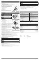
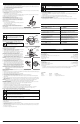
CHARGING THE BATTERY
NOTE: The battery is not shipped fully charged. It is recommended to fully
charge the battery before use to ensure that maximum run time can be
achieved. The lithium-ion battery will not develop a memory and may
be charged at any time. A fully discharged battery will require
approximately 2 hours to completely charge.
1. Plug the charger into an AC wall outlet/ receptacle.
2. The red Power LED will illuminate (Fig. 7).
3. Insert the battery into the charger (Fig. 8).
NOTE: Make sure the battery is fully inserted into the charger by making sure
the red Indicator LED charge light is on (Fig. 7).
4. Once the battery has reached a full charge level the Indicator LED will turn
from red to green (Fig. 7).
5. The battery may be removed or stored in the charger once it is fully charged;
however, it is recommended to disconnect the plug from the wall
outlet/receptacle. To remove the battery, hold down the battery latch and
slide the battery off the charger (Fig. 8).
NOTE: Lithium-ion batteries, while in use, will continue to provide full power
without power fade unlike typical batteries; when the battery is fully
discharged, the battery circuitry will immediately cut power to the tool
and require immediate charging.
Battery Instructions
Press the battery capacity indicator (BCI) button. The lights will illuminate
according to the battery’s current power level (Fig. 9).
INSTALLING AND REMOVING THE BATTERY
Follow these instructions in order to avoid injury and to reduce the risk of electric
shock or fire:
• Verify that the lock-off button is in the locked or OFF position before installing
or removing the battery. Refer to Starting and Stopping Instructions.
• Verify that the battery is removed and the lock-off button is in the locked or OFF
position before inspecting, adjusting or performing maintenance on any part of
the unit.
Installing the Battery
1. Align the tongue of the battery with the handle cavity (Fig. 10).
2. Grasp the rear handle firmly.
3. Push the battery into the handle cavity until the latch locks into place.
4.
Do not use force when inserting the battery. It should slide into position and “click.”
Removing the Battery
1. Press the latch button on the battery down and hold (Fig. 10).
2. Grasp the rear handle firmly and pull the battery out of the handle cavity.
NOTE: The battery fits into the handle cavity snugly in order to prevent
accidental dislodging. It may require a strong pull to remove it.
IMPORTANT! The battery is equipped with an internal circuit breaker that will
automatically shut off power to the unit if the battery is overloaded
during heavy use. Once cooled, the battery will reset itself. Follow
these steps if an overload occurs:
1. Release the switch trigger and then restart the unit. Refer to Starting and
Stopping Instructions.
2. The battery may need to be removed for approximately 1 minute, allowed
to cool and then reinstalled.
3
This unit requires assembly.
UNPACKING
• Carefully remove the product and any accessories from the box.
• Inspect the product carefully to make sure no breakage or damage occurred during shipping.
• Do not discard the packing material until you have carefully inspected and satisfactorily operated the product.
• If any parts are damaged or missing, please call 1-877-282-8684 (U.S.) or 1-800-668-1238 (Canada) for assistance.
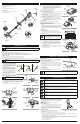
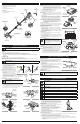
ASSEMBLING THE SHAFT
1. Remove the rubber protector from the end of the upper boom (Fig. 1A and 1B).
2. Unfold the unit so that the lower boom is in line with the upper boom (Fig. 1C).
NOTE: Make sure the coupler buckle is in the clamped position and that the coupler is at the top of its travel area on the lower boom. (Fig. 2).
3. Slide the top of the lower boom shaft into the bottom
of the upper boom shaft and push together until the
coupler is snug against the upper boom. Make sure
the coupler lock button snaps into the hole (Fig. 3).
4. Using a 4mm Allen Wrench tighten the upper Allen
bolt until the coupler is secure and will not move on
the upper boom. (Fig. 4).
INSTALLING AND ADJUSTING THE D-HANDLE
1. Place D-handle over the shaft housing and onto the
bottom clamp (Fig. 5). Place it a minimum of 6
inches (15.24 cm) from the end of the shaft grip.
2. Start the screws with a Phillips screwdriver. Do not
tighten until you make the handle adjustment.
3. While holding the unit in the operating position
(Fig. 12), move the D-handle to the location that
provides you the best grip.
4. Tighten the clamp screws evenly, until the D-handle is secure.
INSTALLING THE CUTTING ATTACHMENT SHIELD
1. Turn the unit over so that the cutting head is facing up (Fig. 6).
2. Using a Philips head screwdriver, remove the three screws from the cutting head.
3. Place the shield over the cutting head and onto the motor housing so that
the decal is facing down and the 3 screw holes line up with the 3 screw pegs
on the motor housing.
4. Install and tighten the screws with a Phillips screwdriver (Fig. 6).
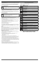
KNOW YOUR UNIT
ASSEMBLY INSTRUCTIONS
APPLICATIONS
This unit may be used for the purposes listed below:
• Cutting grass and light weeds
• Edging
• Decorative trimming around trees, fences, etc.
D-Handle
Switch
Trigger
WARNING: Make sure the motor is off and the battery is disconnected before assembling or disassembling any
components.
Line Cutting
Blade
Shaft
Adjustment
Coupler
Cutting Head
Shield
A
B
C
Fig. 1
Fig. 2
Coupler
Lower Boom
Shaft
Upper Boom
Shaft
STARTING AND STOPPING INSTRUCTIONS
STARTING THE MOTOR
Make sure the immediate area is clear of any objects or obstructions that could
come in contact with the cutting head.
To help prevent accidental start-ups, this unit has a lock-off button and switch
trigger that must be used together to start the unit.
1. Fit the battery into the handle cavity (Fig. 10). Refer to Installing the Battery.
2. Press and hold the lock-off button (Fig. 11). This makes the switch trigger
operational.
3. While holding the lock-off button, press and hold the switch trigger (Fig. 11).
4. Release the lock-off button and continue to squeeze the switch trigger for
continued operation.
STOPPING THE MOTOR
1. Release the switch trigger.
NOTE: Upon release of the switch trigger, the lock-off button will automatically
reset to the locked position.
Switch Trigger
Fig. 11
Lock-off Button
Battery
CAUTION:
When the battery is not installed in the unit,
keep it away from paper clips, coins, keys, nails, screws or
other metal objects that could make a connection from one
terminal to another. Shorting the battery terminals together may
cause sparks, burns or a fire.
Lock-off
Button
Handle
Housing
Shaft Grip
Cutting Head
Multi-purpose
Tool
Battery Charger
Fig. 4
Coupler
Buckle
Allen Bolt
Fig. 5
Shaft Grip
Fig. 6
Cutting Head
Shield
Cutting
Head
Screws (3)
WARNING: To prevent serious damage to the unit, make sure not to let the lower boom drop or pull excessively while
unfolding the unit.
WARNING:
To prevent serious personal injury, never operate
the trimmer without the cutting attachment shield in place.
ASSEMBLY INSTRUCTIONS
Fig. 7
Indicator
LED
Power
LED
Battery
Compartment
Fig. 8
Fig. 9
LED Meter
BCI Button
Fig. 10
Battery
Handle
Housing
Battery Latch
Coupler
Buckle
Screws (4)
Bottom
Clamp
Minimum
6 inches
(15.24 cm)
D-Handle
Shaft Grip
CAUTION: Always allow 5 seconds or more for the cutting head to come to a complete stop after releasing the switch
trigger. Do not invert the unit, or place any body parts near the cutting head until it has come to a complete stop.
OPERATING INSTRUCTIONS
WARNING: If any parts are damaged or missing, do not operate the unit until the parts are replaced. Failure to heed this
warning could result in serious personal injury.
WARNING:
Always wear appropriate eye and ear protection when operating this unit. Wear safety goggles, or safety
glasses with side shields, that are marked as meeting ANSI Z87.1-1989 standards. Failure to do so could result in serious
eye injury caused by thrown objects. If the operation is dusty, wear a facemask or dust mask.
Fig. 12
WARNING: Do not allow familiarity with this unit to promote carelessness. Remember that a careless fraction of a
second is enough to inflict serious injury.
WARNING:
Wear non-slip gloves for maximum grip and protection. Refer to the Safety Information section for
appropriate safety equipment.
WARNING:
Do not expose the unit to rain. Do not use the unit in damp or wet locations or conditions.
WARNING:
To avoid serious injury, do not wear loose fitting garments, such as scarves, strings, chains or ties, which
could be drawn into the air intake. Long hair must be pulled back and secured at the shoulders and neck.
Fig. 3
Coupler
Lock Button
TOOLS REQUIRED:
• 4mm Allen wrench (multi-purpose tool) (included)
• #2 Phillips screwdriver
Battery Latch