
Oil SDS


RECOMBINATION TECHNOLOGY
How gas recombination works:
When a charge current flows through a fully charged conventional lead
acid cell, electrolysis of water occurs to produce hydrogen from the
negative electrode and oxygen from the positive electrode. This means that
water is lost from the cell and regular topping up is needed.
However, evolution of oxygen gas and hydrogen gas does not occur
simultaneously, because the efficiency of recharge of the positive
electrode is not as good as the negative electrode. This means that
oxygen is evolved from the positive plate before hydrogen is evolved from the
negative plate.
At the same time that oxygen is evolved from the positive electrode, a
substantial amount of highly active spongy lead exists on the negative
electrode before it commences hydrogen evolution.
Therefore, provided oxygen can be transported to the negative electrode,
conditions are ideal for a rapid reaction between lead and oxygen:
i.e. This oxygen is electrochemically reduced on the negative electrode
according to the following scheme,
2e
-
+ 2H
+
+
1
/
2
O
2
→ H
2
O
and the final product is water…….
The current flowing through the negative electrode drives this reaction
instead of hydrogen generation which would occur in a flooded cell.
This process is called gas recombination. If this process was 100% efficient, no
water would be lost from the cell. By careful design of the constituents within
the cell, gas recombination up to 99% is achieved.
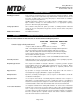
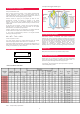
Principle of the oxygen reduction cycle
Figure 1 - Principle of the oxygen reduction cycle
RECOMBINATION EFFICIENCY
Recombination efficiency is determined under specific conditions by
measuring the volume of hydrogen emitted from the battery and converting
this into its amp hour equivalent. This equivalent value is then subtracted from
the total amp hours taken by the battery during the test period and the
remainder is the battery’s recombination efficiency which is usually
expressed as a percentage. As recombination is never 100%, some
hydrogen gas is emitted from NexSys
®
batteries through the self-
regulating valve; the I
gas
value for this technology of battery is 1A/100 Ah C
6
.
NexSys
®
(1)
Approximate
(2)
60% Depth of discharge max
(3)
Can be fitted with SAE terminal
(4 )
Can be fitted with M6 front terminal
NexSys blocs may be configured into a battery comprising series/parallel
arrays, with the maximum number of parallel strings limited to three. It is
paramount that the cable lengths within each string are equal.
Only EnerSys
®
approved components / parts may be used in conjunction
with the NexSys battery product.
BATTERY CONFIGURATIONS
ORIENTATION
NexSys
blocs can be mounted in any orientation except inverted.
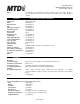
RANGE SUMMARY
Terminal layout 2
Terminal layout 1
3
R
Table 1 – NexSys
®
battery specifications
RANGE SUMMARY AVAILABLE.