
Product Manual

8
ASSEMBLY
NOTE: This Operator’s Manual covers several models. Tractor
features may vary by model. Not all features in this manual are
applicable to all tractor models and the tractor depicted may
differ from yours.
NOTE: All references in this manual to the left or right side and
front or back of the tractor are from the operating position only.
Exceptions, if any, will be specified.
Preparation
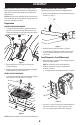
MANUALLY MOVING THE TRACTOR
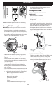
1. To engage the transmission bypass, pull the transmission
bypass lever (a) located to the right of the operator’s seat
(next to the park brake lever (b)), back and into the notch on
the right side of the slot. See Figure 1.
(b)
(a)
Figure 1
2. After moving tractor, reverse Step 1 to disengage the
transmission bypass.
3. Remove the deck wash system nozzle adapter (if equipped)
from the manual bag, store for future use.
INSTALL HITCH IF NECESSARY
1. Locate hitch (a) and install on the rear of the frame using the
two hex washer screws (b) provided. See Figure 2.
(a)
(b)
(b)
Figure 2
NOTE: Hitch and hex washer screws will be in the hardware pack.
REPOSITION UPPER HOOP IF NECESSARY
Upper hoop may be positioned down for shipping purposes:
1. Remove the two hex washer screws (a) partially installed on
the frame. See Figure 3.
(a)
(b)
(b)
Figure 3
2. Rotate the upper hoop (b) into position. See Figure 3.
3. Secure hoop in place with the hex washer screws removed
in Step 1. Torque the hex washer screws to 159-239 in-lbs
(18-27 N-m).
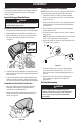
Install Operator’s Seat (If Necessary)
1. Remove any straps securing the seat assembly to the tractor.
Remove all packing material.
NOTE: Be careful not to cut the seat wiring harness.
2. Install the seat onto the seat pan (c) using hardware
provided. See Figure 4.
a. Use flange lock nuts (a) and flat washers (b). See Figure 4.
(a)
(a)
(b)
(b)
(c)
(a)
(a)
Figure 4
3. If necessary, securely connect the seat switch wiring harness
(a) to the seat switch (b). See Figure 5 on page 9. Secure
excess wire away from pinch points before continuing.