Cat. No. 01015170 Rev. A 09/24/02 DCO# 4541 Service Manual HOUSEHOLD & COMMERCIAL CIRCUIT BOARDS Models From 1994 - 2002 ©2002 Culligan International Company Printed in U.S.A.
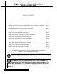
Culligan Household and Commercial Circuit Boards Models From 1994 - 2002 TABLE OF CONTENTS Culligan Medallist Series™ Circuit Board Page 1 Culligan® Mark 100 Generation I Circuit Board Page 9 Culligan® Mark 100 Generation II/ Culligan Platinum Series™ Generation I Circuit Board Page 14 Culligan® Mark 100 Generation III, Culligan Silver Series™, Culligan Gold Series™ and Culligan® Platinum Series™ Generation II Circuit Boards Page 21 Upgrade Kit to Convert Culligan® Mark 100 Generation I Circuit Bo
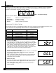
Culligan Medallist Series™ Circuit Board Used from 1/01 to Current Replacement PN: 01014172 Control Functions Function Time of Day Time of Regen. Salt Dosage Backwash Time Brine Rinse Time Gallons Capacity/Regen. Interval Forced Regen. Interval Lock/Unlock display Time Clock YES YES YES YES YES YES NO YES Soft-Minder Meter YES YES YES YES YES YES YES* YES Default 12:00 p.m. 2:00 a.m. 10 lbs. 10 min. 71 min 870 gallons or 3 days disabled disabled * When Time Clock Backup is set to "ON".
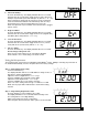
Programming Make sure the inlet water supply is turned off, then supply power to the timer. The display will power up flashing "12:00 PM" and the motor will energize and cycle the control, without stopping, to the home position. This is required to ensure that the control is in the home position. FIG. 3 - Circuit Board Display The timer uses four buttons: 1. 2. 3. 4. STATUS: PLUS SIGN "+": MINUS SIGN "-": REGEN.: Advance timer through display options. Increase the setting. Decrease the setting.
Programming OFF 4. Timeclock Backup Press the “STATUS” key. The display will blink “dIP4” for 3 seconds and then show the current status. Toggle between “OFF” (Timeclock backup is off) and “ON” (Timeclock backup is on) with the “+” or “-” key. Note: Changing this setting will not change any of the programmed values and will load the default Timeclock Backup value of 3 days. Programming step 7 will be activated when this is set to On.
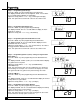
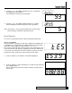
Programming Step 3 – Programming Salt Dosage Press the “Status” key after programming regeneration time. The display will blink “SLtP” if set to English or “SLtG” if set to Metric for 3 seconds and then display the salt dosage. Adjust the setting with the “+” or “-” key (3-24 lbs.)(0.5-10.0 kgs.) Note: This option will not show if the control is set to Filter mode. Step 4 – Programming Backwash Time Press the “Status” key after programming salt dosage.
Programming Exiting Program Mode From Step 6 (or step 7 if it is active) press the “Status” key. The display will go blank. Press the “Status” key again to exit programming. Note: The control will exit the programming mode if no key press activity takes place within one minute. Locking the Programmed Menu Press and hold the “+” key for 3 seconds while in the service mode. The display will show the status of the lock feature. (“LoC” or “unL”) Adjust with the “+” or “-“ key.
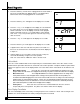
Manual Cycling 5. Press the “+” key. An 'H' will appear in the display. The unit is in the HOME position. The 'REGEN' enunciator is no longer blinking. 6. Press the status key. Time-of-Day appears in the display. Note: If the valve is manually cycled from any position, the # regen counters will not be updated.
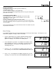
Service Check 5. Press the “-” key. The display will blink “totL” for 3 seconds and then display the total number of regenerations this control has cycled through. 93 6. Press the “-” key. The display will blink “daYS” for 3 seconds and then display the number of days since last regeneration. Note: Pressing the “+” key at any time brings back to manual cycling. Pressing “Status” will Exit the programming menu.
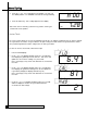
Board Diagnostics 3. Press the status key. If a flow meter is plugged into the circuit board, a bar on the second digit of the display will be lit. The display will be blank if a flow meter is not plugged into the circuit board. 4. Press the status key. A “1” will appear on the display for 3 seconds. 5. Press the “+” key. A “2” will appear on the display for 3 seconds and the motor will run. An “H” in the display means the motor homing switch is activated.
Culligan® Mark 100 Generation 1 Circuit Board Used from 7/94 to 6/98 Replacement PN: 01-0042-94 - 110 volt 01-0063-24 - 24 volt Status: Obsolete, replace with 01-0146-64 Control Functions FUNCTION TIME CLOCK SOFT MINDER METER AQUA-SENSOR DEFAULT 1. Time of Day Yes Yes Yes 12:00 AM 2. Time of Regeneration Yes Yes Yes 2:00 AM 3. Salt Dosage Yes Yes Yes 4. Backwash Time Yes Yes Yes 10 min. 5. Brine Ruse Yes Yes Yes 71 min. for 9”; 59 min. for 12” 6.
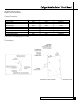
Connections Dip Switch Cam Connection Aqua-Sensor Connection Meter Connection Power Connection Programming Upon plugging in the Culligan® Mark 100 control, the display will flash 8888. To access the programming mode, press the status button. Refer to diagrams below for the programming sequence. 1. Plug in. Press status. 12:00 will appear. 1 Press 2. Press status. 12 Press I2:00 2:00 Set Recharge Time. ALL MODELS. Step 3 is currently not used. 8 Set Salt Dosage (3-15 lb for 9”, 5-24 lb for 12”).
Programming 5. Press status. 7I 5 Press to increase or to decrease 6. Press status. 123 Press 456 Press Set Hardness Level (1-75 gpg for 9”, 1-99 gpg for 12”). METER MODELS ONLY. 20 to increase or to decrease 7. Press status. 123 Set Brine Rinse Time (37-85 minutes for 9”, 35-89 minutes for 12”). TIME CLOCK AND METER MODELS ONLY. Set Regeneration Interval (1-42 days). TIME CLOCK MODELS ONLY.
Cycling The Culligan® Mark 100 control can be indexed through the various regeneration stages. 1. Press the STATUS key until the display is blank. 2. Press the REGEN key. Press UP arrow. 3. Press the UP arrow. 4. Press the UP arrow. 5. Press the UP arrow. 6. Press the STATUS key twice. 12 CULLIGAN HOUSEHOLD & COMMERCIAL CIRCUIT BOARDS Display in blank. REGEN 10 A “1” appears in the display. REGEN flashing. The Unit is now in backwash. 20 A “2” appears in the display. REGEN flashing.
Cycling Board Diagnostic To enter the board test mode, shift the Aqua-Sensor® sensing device and the Soft-Minder® meter dip switches (#1 and #2) to the ON position (upwards). The display will initially light up all segments until either a key is depressed, an option is changed, or a CAM microswitch changes position. Pressing one of the keys, closing a microswitch, or turning on a dip switch will light a different segment as outlined in table 3.
Culligan® Mark 100 Generation II/Culligan Platinum Series Generation I Circuit Board Used from 6/98 to 5/26/2000 Status: Obsolete, replace with 01-0130-94 (Culligan® Mark 100 Control) Obsolete, replace with 01-0141-74 (Culligan Platinum Series™ Control) Control Function FUNCTION TIME CLOCK SOFT MINDER METER DEFAULT 1. Time of Day Yes Yes 12:00 AM 2. Time of Regeneration Yes Yes 2:00 AM 3. Not Used No No 10 min. 3b. East Rinse Time Yes Yes 10 min. 4.
Connections Programming The display will initially power up flashing "8888". After 1 minute the motor will energize and cycle the control, without stopping, to the home position. This is required to ensure that the control is in the home position. FIG. 3 - Circuit Board Display The timer uses four buttons: 1. 2. 3. 4. STATUS: UP ARROW: DOWN ARROW: REGEN.: Advance timer through display options. Increase the setting. Decrease the setting. Initiate a manual regeneration.
Setting The Microprocessor The microprocessor senses when it is installed as a Soft-Minder or Aqua-Sensor® control. Adding or removing any connection to the board, or flipping any of the dip switches will automatically reset the microprocessor to the factory settings. 1. With a flashing or blank display, pressing the status button twice will move to the Time-of-Day adjustment, adjust the time by using the up and down arrows. A number “1” will appear at the bottom of the display while in this mode.
Setting The Microprocessor 8. Press status again to display the Hardness Level in grains per gallon. The setting can be adjusted from 2-99 gpg by using the up and down arrows. This screen will not appear when the Aqua-Sensor® probe is attached. A number “7” will appear at the bottom of the display while in this mode. Press to increase or to decrease Press to increase or to decrease Press simultaneously Press to change Press to change Press simultaneously 9.
Service Check The service check mode allows one to view the instantaneous flow rate, the days since the last regeneration, the total number of regenerations, the regenerations in the past fourteen days, and the gallons remaining. To enter the service check mode, follow these steps: 1. Press the status key to move past steps 1-10 until the display is blank. 2. Push the down arrow. The number '12' will appear only when the Soft-Minder® meter is connected. The display reads the gallons per minute flow rate.
Manual Cycling The Culligan® microprocessor can be indexed through the various regeneration stages. For all steps, the cycle numbers do not appear, or change, until the motor stops. 1. Press the status button to move past steps 1-10 until the display is blank. Push the up arrow. The number “11” icon will light up. An "H" will appear in the display. The control is in the HOME position. Pressing the regen button once will light the 'REGEN' icon. 2. Press the regen button one more time.
Board Diagnostics To enter the board test mode, flip all of the dip switches to the ON position. All the segments of the board will light until either a key is depressed, an option is changed or a CAM micro switch changes position. Pressing one of the keys, closing a micro switch or turning OFF a dip switch will cause a different segment to light as outlined in Table 10.
Culligan Silver Series™, Culligan Gold Series™, Culligan® Mark 100 Generation III, & Culligan Platinum Series Circuit Board Used from 6/00 to Current Products: Culligan® Mark 100 Generation III, Culligan Silver Series™, Culligan Gold Series™, and Culligan Platinum Series™ Controls Replacement PN: 01-0130-94 -- Culligan® Mark 100 Generation III, Culligan Silver Series™, Culligan Gold Series™ 01-0141-74 -- Culligan Platinum Series™ Controls Control Functions TIME CLOCK SOFT-MINDER METER AQUA-SENSOR FUNCTION
Connections Programming The display will initially power up flashing "12:00 PM". After 1 minute the motor will energize and cycle the control, without stopping, to the home position. This is required to ensure that the control is in the home position. FIG. 3 - Circuit Board Display The timer uses four buttons: 1. 2. 3. 4. STATUS: UP ARROW: DOWN ARROW: REGEN.: Advance timer through display options. Increase the setting. Decrease the setting. Initiate a manual regeneration.
Programming 5. 6. 7. 8. 9. Pressing status again will show the Salt Dosage. This can be adjusted with the up and down arrows, the range is 3-15 lbs. for the 9” controls and 5-24 lbs. on 12” controls. A number “4” will appear at the bottom of the display while in this mode. 4 Press to increase or to decrease Press to increase or to decrease Press status again, this displays the Backwash Time in minutes. The setting can be adjusted between 5 and 40 minutes by using the up and down arrows.
Manual Cycling The Culligan® microprocessor can be indexed through the various regeneration stages. For all steps, the cycle numbers do not appear, or change, until the motor stops. 1. Press the status button to move past steps 1-10 until the display is blank. Push the up arrow. The number “11” icon will light up. An "H" will appear in the display. The control is in the HOME position. Pressing the regen button once will light the 'REGEN' icon. 2. Press the regen button one more time.
Service Check The service check mode allows one to view the instantaneous flow rate, the days since the last regeneration, the total number of regenerations, the regenerations in the past fourteen days, and the gallons remaining. To enter the service check mode, follow these steps: 1. Press the status key to move past steps 1-10 until the display is blank. 2. Push the down arrow. The number '12' will appear only when the Soft-Minder® meter is connected. The display reads the gallons per minute flow rate.
Board Diagnostics To enter the board test mode, flip all of the dip switches to the ON position. All the segments of the board will light until either a key is depressed, an option is changed or a CAM micro switch changes position. Pressing one of the keys, closing a micro switch or turning OFF a dip switch will cause a different segment to light as outlined in Table 10.
Installation Instructions Converting the Culligan Mark 100 Generation I Circuit Board to a Generation III Circuit Board Familiarize yourself with the replacement procedures and component parts before attempting any repair. WARNING! DISCONNECT ALL ELECTRICAL POWER TO THE UNIT BEFORE SERVICING. INSTALLATION 1. 2. Remove the timer cover by twisting the four, quarter turn Phillips screws. Remove the power, microswitch and motor leads from the board. Remove the motor leads from the motor.
Wiring Schematic 28 CULLIGAN HOUSEHOLD & COMMERCIAL CIRCUIT BOARDS
Culligan® Aqua-Sensor® Sensing Device Troubleshooting The following procedure will help you diagnose problems in units equipped with Aqua-Sensor sensing device. Because many “sensor problems” are actually regeneration problems, it contains a combination of sensor diagnostics and routine control valve and brine system checks. Refer to the Troubleshooting Flow chart on page 3 for the recommended sequence. Circuit Board Test 1) Identify the circuit board generation (See Fig. 1 for Generation 1, Fig.
Culligan® Aqua-Sensor® Sensing Device Troubleshooting Continued Probe Test Run this test only on a circuit board that has passed the Circuit Board Test, above. 1) Remove the probe from the resin tank. 2) Visual inspection a) Look for discoloration (brown film or blue spots) on electrode fins. b) If discolored, try cleaning the probe (Sofner-Gard chemical or white vinegar). The fins can be lightly scrubbed with a soft toothbrush.
Troubleshooting Flowchart Problem: Diagnostics Sequence: Regenerates Nightly Never Regenerates Check water usage: higher than expected? Is there salt in the brine tank? Gen 3: Check step 6. The default setting is 71 minutes. If it has been reduced, restore it to at least the default setting. Does the unit draw brine properly? Initiate a manual regeneration; is water soft? Check eductor nozzle and screen for plugging or fouling. Test circuit board & probe. Test circuit board & probe. Check resin.
Culligan® Mark 10 and Estate 2M Generation I Circuit Board Used from 11/95 to 2/98 Replacement PN: 01-0063-22 - 110 volt 01-0063-23 - 24 volt Status: Obsolete, replace with 01-0129-63 - 110 volt 01-0148-93 - 24 volt PROGRAMMING SWITCHES CAPACITY GALLONS SW 2 SWITCH SETTINGS SW 3 SW 4 300 600 900 1200 1600 2000 2500 3000 ON ON ON ON OFF OFF OFF OFF ON ON OFF OFF ON ON OFF OFF ON OFF ON OFF ON OFF ON OFF SW 1 RUN ON TEST OFF There is one pilot light located on the circuit board.
Connections Dip Switches Amber LED Reset Switch Connection Regen Button Connection Meter Connection Power Connection CULLIGAN HOUSEHOLD & COMMERCIAL CIRCUIT BOARDS 33
Culligan® Mark 10 and Estate 2M Generation I I Circuit Board Used from 2/98 to 12/99 Replacement PN: 01-0101-27 - 110 volt Programming Switches CAPACITY GALLONS 10 100 200 300 400 500 600 700 800 900 1000 1100 1200 1300 1400 1500 1600 1700 1800 1900 2000 2100 2200 2300 2400 2500 2600 2700 2800 2900 3000 3100 34 SW 2 OFF ON OFF ON OFF ON OFF ON OFF ON OFF ON OFF ON OFF ON OFF ON OFF ON OFF ON OFF ON OFF ON OFF ON OFF ON OFF ON CULLIGAN HOUSEHOLD & COMMERCIAL CIRCUIT BOARDS SW 3 OFF OFF ON ON OFF OFF ON
Connections There are two pilot lights located on the circuit board. • The green pilot light flickers when water is flowing through the water meter. • The amber pilot light is a latching indicator, when the preset gallons count has passed, the amber light will illuminate indicating that the unit will regenerate that night. The softener also has a ten gallon setting to assist the service personnel in trouble shooting the equipment. To trouble shoot the meter, set the dip switches to the OFF position.
Installation Converting the Culligan Mark 10/Estate 2M Generation I Circuit Board to a Generation II Circuit Board WARNING: DISCONNECT ALL ELECTRICAL POWER TO THE UNIT BEFORE SERVICING. Electrical shock hazard – will cause personal injury or death. • • • • Unplug the electric power cord. Remove the control cover and timer mechanism. Remove the flow meter harness, reset/regeneration harness and circuit board harness from the circuit board. Remove the circuit board from the supporting bracket.
Wiring Connections Power Valve CAUTION: Refer to the wiring schematic diagram for correct plug in reference of wire harness connectors. Do not touch any surface of the circuit board. Electrical static discharges can damage the circuit board. Handle the circuit board by its edges. • • • • • • • Insert the circuit board into the supporting bracket.
Wiring Diagram • Power Valve 38 CULLIGAN HOUSEHOLD & COMMERCIAL CIRCUIT BOARDS
Wiring Diagram • Delrin Valve CULLIGAN HOUSEHOLD & COMMERCIAL CIRCUIT BOARDS 39
Culligan® Commercial Generation I Circuit Board Used from 6/98 to 5/26/00 Status: Obsolete, replacement with PN: 01-0128-38 Control Functions 1. 2. 3. 4. 5. 6. 7. 8. FUNCTION Time of Day Time of Regeneration Not Used Pulse/Gallon Backwash Time Brine Rinse Time Fast Rinse/Refill Time Gallon Capacity / Regen. Interval 9. Total Gallons Since Last Circuit Board Reset 10.
Connections Comm.
Connections ® 42 CULLIGAN HOUSEHOLD & COMMERCIAL CIRCUIT BOARDS
Connections CULLIGAN HOUSEHOLD & COMMERCIAL CIRCUIT BOARDS 43
Programming 1. Turn on the power to the control. 2. Display will be flashing. 3. Press status twice; 12:00 PM will appear, this is the time of day, adjust using the up and down arrows. A number "1" will appear at the bottom of the display while in this mode. to increase or to decrease 4. Press status again, this displays the time of regeneration for time clock and delayed units, adjust using the up and down arrows. A number "2" will appear at the bottom of the display while in this mode.
Programming 9. Press status again, if the unit is a time-clock model the display will show the number of days desired between regenerations. The setting can be adjusted using the up and down arrows. If the unit is a metered unit this will display the number of gallons desired between regenerations. Step 8 will be skipped for Aqua-Sensor mode unless dip switch 10 is set to ON for time clock backup. A number "8" will appear at the bottom of the display while in this mode.
Service Check The service check mode allows one to view the instantaneous flow rate, the days since the last regeneration, the number of regenerations in the past fourteen days and the gallons remaining. To enter the service check mode, follow these steps: 1. Press the STATUS key until the display is blank. Press the UP arrow to access step 11. 2. Push the DOWN arrow. The number 12 will appear if the flow meter is connected. The display reads the gallons per minute flow rate. 3. Press the DOWN arrow.
Manual Cycling The Culligan® Electronic control can be indexed through the various regeneration stages. For all steps, the cycle numbers do not appear until the motor stops. 1.Press the STATUS button until the display is blank. Push the UP arrow. An “H” will appear in the display. The number 11 icon will light up. The control is in the HOME position. 2.Press the REGEN button twice. The REGEN icon will light and blink. A “1” will appear. The unit is now in the BACKWASH position.
Diagnostic Board Diagnostic To enter the board test mode, turn all the dip switches to the ON position. All segments of the board will light until either a key is pressed, an option is changed, or a cam microswitch changes position. Pressing one of the keys, closing a microswitch or moving a dip switch to the OFF position will cause a different segment to light as outlined in Chart 1. Duplex Parallel Operation 1. 2. 3. 4. Dip switch 6 should be in the ON position.
Culligan® Commercial Generation II Circuit Board Used from 5/26/00 to current Replacement PN: 01-0128-38 Control Functions 1. 2. 3. 4. 5. 6. 7. 8. FUNCTION Time of Day Time of Regeneration Not Used Pulse/Gallon Backwash Time Brine Rinse Time Fast Rinse/Refill Time Gallon Capacity / Regen. Interval 9. Total Gallons Since Last Circuit Board Reset 10. Lock/Unlock Display Blanking Feature MODEL TYPE All Timeclock & Delayed NO Meter All YES NO Timeclock Meter Meter DEFAULT 12:00 AM 2:00 AM NA 10.0 10 min.
Connections ® Single Flow Meter & Single AquaSensor® Circuit Board Connections 50 CULLIGAN HOUSEHOLD & COMMERCIAL CIRCUIT BOARDS
Connections Duplex Parallel Flow Meter Circuit Board Connection Duplex Parallel Aqua-Sensor® Circuit Board Connections CULLIGAN HOUSEHOLD & COMMERCIAL CIRCUIT BOARDS 51
Connections Duplex Alternating Flow Meter Circuit Board Connections (See Fig. 11 for tubing instructions) ® Duplex Alternating Aqua-Sensor® Circuit Board Connection (See Fig.
Programming 1. Turn on the power to the control. 2. Display will be flashing. 3. Press status twice; 12:00 PM will appear, this is the time of day, adjust using the up and down arrows. A number "1" will appear at the bottom of the display while in this mode. to increase or to decrease 4. Press status again, this displays the time of regeneration for time clock and delayed units, adjust using the up and down arrows. A number "2" will appear at the bottom of the display while in this mode.
Programming 9. Press status again, if the unit is a time-clock model the display will show the number of days desired between regenerations. The setting can be adjusted using the up and down arrows. If the unit is a metered unit this will display the number of gallons desired between regenerations. Step 8 will be skipped for Aqua-Sensor mode unless dip switch 10 is set to ON for time clock backup. A number "8" will appear at the bottom of the display while in this mode.
Service Check The service check mode allows one to view the instantaneous flow rate, the days since the last regeneration, the number of regenerations in the past fourteen days and the gallons remaining. To enter the service check mode, follow these steps: 1. Press the STATUS key until the display is blank. Press the UP arrow to access step 11. 2. Push the DOWN arrow. The number 12 will appear if the flow meter is connected. The display reads the gallons per minute flow rate. 3. Press the DOWN arrow.
Manual Cycling The Culligan® Electronic control can be indexed through the various regeneration stages. For all steps, the cycle numbers do not appear until the motor stops. 1.Press the STATUS button until the display is blank. Push the UP arrow. An “H” will appear in the display. The number 11 icon will light up. The control is in the HOME position. 2.Press the REGEN button twice. The REGEN icon will light and blink. A “1” will appear. The unit is now in the BACKWASH position.
Diagnostic Board Diagnostic To enter the board test mode, turn all the dip switches to the ON position. All segments of the board will light until either a key is pressed, an option is changed, or a cam microswitch changes position. Pressing one of the keys, closing a microswitch or moving a dip switch to the OFF position will cause a different segment to light as outlined in Chart 1. Duplex Parallel Operation 1.Dip switch 6 should be in the ON position. 2.