Cat. No. 01882319 Rev.
Attention Culligan Customer: The installation, service and maintenance of this equipment should be rendered by a qualified and trained service technician. Your local independently operated Culligan dealer employs trained service and maintenance personnel who are experienced in the installation, function and repair of Culligan equipment. This publication is written specifically for these individuals and is intended for their use.
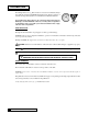
Installation and Operating Instructions CULLIGAN SILVER SERIES™ AUTOMATIC WATER CONDITIONER MODELS FROM 2001 Table of Contents Page Introduction ............................................................... 2 Specifications ............................................................ 3 Preparation ............................................................... 4 Installation ................................................................. 6 Settings .....................................................
Introduction The Culligan Silver Series™ Water Softeners are tested and validated by WQA and certified by UL against ANSI/NSF Standard 44 for the effective reduction of calcium and magnesium (hardness) as well as Barium and Radium 226/228*. For installations in Massachusetts, the Commonwealth of Massachusetts Plumbing Code 248 CMR shall be adhered to. Consult your licensed plumber for installation of the system. This system and its installation must comply with state and local regulations.
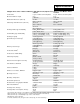
Specifications Culligan Silver Series™ Water Conditioners with Time Clock, Aqua-Sensor® Device or Soft-Minder® Meter Control Valve Overall Conditioner Height Media Tank Dimensions (Dia x Ht) Salt Storage Tank Dimensions (Dia x Ht) Exchange Media, Type and Quantity Underbedding, Type and Quantity Exchange Capacity @ Salt Dosage Per Recharge1 Efficiency rated dosage1 Freeboard to Media2 Freeboard to Underbedding3 Salt Storage Capacity Rated Service Flow @ Pressure Drop Total Hardness, Maximum Total Iron, Ma
Preparation COMPONENT DESCRIPTION The water conditioner is shipped from the factory in a minimum of four cartons. Remove all components from their cartons and inspect them before starting installation. Control Valve Assembly - Includes the 5-cycle regeneration control valve and the Accusoft® Microprocessor. Small parts packages will contain additional installation hardware. Installation and Operations Instructions and an Owner’s Guide are included.
Temperature - Do not install the unit where it might freeze, or next to a water heater or furnace or in direct sunlight. LOCATION Space requirements - Allow 6-12 inches (15-30 cm) behind the unit for plumbing and drain lines and 4 feet (1.3 meters) above for service access and filling the salt container. Floor surface - Choose an area with solid, level floor free of bumps or irregularities.
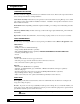
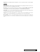
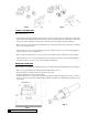
Installation PLACEMENT Refer to Figure 1 for system placement. • Set the media tank on a solid, level surface near water, drain and electrical facilities. Place the outlet (black coupling) of the tank on the left. • Set the brine system on a flat, smooth, solid surface as near the media tank as possible. MOUNT THE CONTROL VALVE See Figure 2 for a visual on mounting the control valve to the tank. • Remove and discard the protective covers on the tank couplings.
FIG. 2 PLUMBING CONNECTIONS FIG. 3 Two methods of connecting the water softener to the plumbing system are available. Shipped with each softener is a Culligan® Cul-Flo-Valv® bypass valve, either PN 01-0124-88 or 01-0102-38, which is used to connect the softener to the plumbing system. The bypass allows the softener to be isolated from the water service line if service is necessary while still providing water to the house.
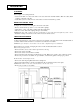
FIG. 4 FIG. 5 CONNECT THE BRINE LINE Refer to Figures 6 & 7. • Use the length of brine line included in the brine tank, or measure a length of brine line sufficient to reach from the brine tank to the brine fitting, with no sharp bends. For easier access to the float it is recommended to add an extra four feet (1.3 meters) of length to the brine line. Cut both ends of the brine line squarely and cleanly.
NOTICE: Waste connections or drain outlets shall be designed and constructed to provide for connection to the sanitary waste system through an air gap of 2 pipe diameters or 1 inch, whichever is larger. NOTICE: Observe all plumbing codes. Most codes require an anti-siphon device or air gap at the discharge point. The system and installation must comply with state and local laws and regulations.
TABLE 1 - DRAIN LINE LENGTH AND HEIGHT LIMITATIONS 9-INCH MODELS Average Water Pressure Height of Drain Discharge Above Floor Upon Which Softener Sets psi 4 in. 1 ft 2 ft 3 ft 4 ft 5 ft 6 ft 7 ft 8 ft 9 ft 10 ft kPa 0.1 m 0.3 m 0.6 m 0.9 m 1.2 m 1.5 m 1.8 m 2.1 m 2.4 m 2.7 m 3.1 m 30 56 50 40 30 20 10 210 17.1 15.3 12.2 9.2 6.1 3.1 50 112 106 96 86 76 66 56 46 36 26 16 350 34.2 32.3 29.3 26.2 23.2 20.1 17.1 14.0 11.0 7.9 4.
Settings The mircoprocessor can be set in three distinct operation modes. Aqua-Sensor® Sensing Device, Soft-Minder® meter, or Timeclock. As shipped from the factory, the control is set for 9" Timeclock operation. A set of dip switches, located on the back of the control, may have to be changed for proper operation of the unit. Refer to Figure 12 and Table 3 for the proper setting of these dip switches.
The progamming for the time clock models is limited to Time-of-Day, Time-of-Regeneration, Salt dosage, Backwash Time, Brine/Rinse Time, and the Regeneration Interval. The numeric enunciator will only light for those programming options (numbers 1-6, and 8-10). Refer to the programming section for further information on programming the microprocessor. CAPACITY AND SALT SETTINGS The microprocessor calculates the total gallon capacity based on the salt dosage, water hardness and tank size.
DIP SWITCH SETTINGS The microprocessor has several dip switches that can be switched for various additional functions. Listed are the functions for the dip switches used on the Mark 100 control. Dip Switch Function 4 9" - 12" Tank Settings 6 Delay vs. Immediate Regeneration 7 English vs. Metric Settings 8 12 or 24 Hour Clock 10 Time Clock Backup Default (OFF) Position 9" Tank Delayed Regeneration English Settings 12 Hour Clock No Forced Regeneration Refer to Figure 11 for setting the dipswitches.
Programming Make sure the inlet water supply is turned off, then supply power to the timer. The display will power up flashing "12:00 PM". After 1 minute the motor will energize and cycle the control, without stopping, to the home position. This is required to ensure that the control is in the home position. FIG. 12 - Circuit Board Display The timer uses four buttons: 1. 2. 3. 4. STATUS: UP ARROW: DOWN ARROW: REGEN.: Advance timer through display options. Increase the setting. Decrease the setting.
5. 6. 7. Press status again, this displays the Backwash Time in minutes. The setting can be adjusted between 5 and 40 minutes by using the up and down arrows. A number “5” will appear at the bottom of the display while in this mode. Press ▲ to increase or ▼ to decrease Press ▲ to increase or ▼ to decrease Press status again to display the Brine/Rinse Time in minutes. The settings can be adjusted using the up and down arrows (35-99 min).
16 CULLIGAN SILVER SERIES™ WATER SOFTENER (23.5) (37.5) 15-3/4 (40.0) 21-3/4 (55.2) (26.9) 11-3/8 (19.1) 7-1/2 IN (CM) 375 LB CAPACITY TO SIGNAL TOTAL CAPACITY CAPACITY TO SIGNAL TOTAL CAPACITY (11.7) (19.7) 12 8 4-5/8 7-3/4 4 (40.0) (55.2) (23.5) 15-3/4 (37.5) 21-3/4 9-1/4 14-3/4 IN (CM) IN (CM) DOSAGE 250 LB 160 LB SALT "A" DIMENSION (26.9) 11-3/8 (19.1) 7-1/2 (8.
PROGRAMMING 17 (40.0) 17-1/4 (43.8) 24-1/2 (62.2) (28.9) 11-3/8 IN (CM) 375 LB CAPACITY TO SIGNAL TOTAL CAPACITY CAPACITY TO SIGNAL TOTAL CAPACITY (18.7) (37.5) 18 12 7-3/8 14-3/4 6 17-1/4 (43.8) (62.2) (28.9) 11-3/8 (14.0) 5-1/2 IN (CM) 375 LB 24-1/2 (40.0) (56.
Manual Cycling The Culligan® microprocessor can be indexed through the various regeneration stages. For all steps, the cycle numbers do not appear, or change, until the motor stops. 1. Press the status button to move past steps 1-10 until the display is blank. Push the up arrow. The number “11” icon will light up. An "H" will appear in the display. The control is in the HOME position. Pressing the regen button once will light the 'REGEN' icon. 2. Press the regen button one more time.
Service Check The service check mode allows one to view the instantaneous flow rate, the days since the last regeneration, the total number of regenerations, the regenerations in the past fourteen days, and the gallons remaining. To enter the service check mode, follow these steps: 1. Press the status key to move past steps 1-10 until the display is blank. 2. Push the down arrow. The number '12' will appear only when the Soft-Minder® meter is connected. The display reads the gallons per minute flow rate.
Operation DISPLAY There are two display modes on the Culligan® microprocessor. As shipped from the factory, the display of the board is initially set to turn off if there has been no keyboard activity after a 1 minute period. Touching any key will relight the display. The display can be set so that it will always display the time. For information on changing the display lighting option, refer to the programming section.
BEFORE LEAVING THE INSTALLATION SITE Flush the sanitizing solution from the unit by running it to drain for a minimum of 40 gallons, or initiate a full recharge cycle (by pushing the 'REGEN.' button twice). Ensure that the brine tank has water to the level of the float. Add water to the tank with a hose or put the unit into a full recharge so that the brine refill cycle will fill the tank with the proper amount of water. The water heater will hold hard water for several days.
Sanitizing Instructions A water softener in daily use on a potable water supply generally requires no special attention other than keeping the salt tank filled. Occasionally, however, a unit may require sanitation under one of the following conditions: • • The unit has stood idle for a week or more (the premises vacant or the residents on vacation). On private supplies, the appearance of off-tastes and odors, particularly a musty or "rotten egg" odor .
Parts List - Tank Assembly Item Part Number * 01006463 * 01010135 * 01003757 * 01003758 * 01004297 * 01004300 * 01004298 * 01004299 1 2 01007281 01010328 01010329 P0232007 P0333957 4 5 Description Tank Assembly, 9" Aqua-Sensor®, Complete Tank Assembly, 12" Aqua-Sensor, Complete Tank Assembly, 9" Soft-Minder®, Complete Tank Assembly, 12" Soft-Minder, Complete Tank Replacement, 9" Aqua-Sensor, Empty Tank Replacement, 12" Aqua-Sensor, Empty Tank Replacement, 9" Soft-Minder, Empty Tank Repla
Parts List - Control 24 CULLIGAN SILVER SERIES™ WATER SOFTENER
CONTROL VALVE PARTS LIST 25 Control Valve Assembly - Silver Series Control Valve Seal Pack Assembly Eductor Sleeve and Eductor Piston Assembly O-Ring, Eductor Sleeve, Small O-Ring (25/Kit) O-Ring, Eductor Sleeve, Large O-Ring (25/Kit) Screen, Eductor Sleeve (10/Kit) O-Ring, Eductor Piston (10/Kit) Connector Brine Line Insert, PP, 0.312" (25/Kit) Nut, PP, 0.
Parts List - Salt Storage Tank Item Part Number — — — † 1 2 3 * * 00441390 00441886 00441887 01004870 00303993 00401042 00303980 00304010 00441391 00303975 00304430 00304439 Description Brine System, 160 lb. Replacement Brine System, 250 lb. Replacement Brine System, 375 lb. Replacement Gold Band Cover with Band, 250 lb. (114 kg) Cover with Band, 160 lb. (73 kg) Cover with Band, 375 lb. (170 kg) Tank Only, 250 lb. (114 kg) Tank Only, 160 lb. (73 kg) Tank Only, 375 lb.
Parts List - Brine Well & Float Item Part Number — — 1 2 3 ‡4 ‡5 6 00441888 00401141 00303193 00303192 00440796 00308407 00401622 00340014 7 ‡8 9 00440795 00332528 00223435 10 11 12 13 14 ‡15 16 17 ‡18 19 00304703 00304718 00444873 00332072 00444664 00444496 00447392 00447781 00304804 00541821 00541834 20 00304537 21 * * 00441392 00304606 00446388 00446389 Description Brine Valve Assembly Brine Valve Assy., Brine Tank, 160 lb.