
Operating instructions


INSTALLATION 7
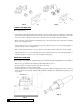
FIG. 2
FIG. 3
PLUMBING CONNECTIONS
Two methods of connecting the water softener to the plumbing system are available. Shipped with each softener is
a Culligan
®
Cul-Flo-Valv
®
bypass valve, either PN 01-0124-88 or 01-0102-38, which is used to connect the softener
to the plumbing system. The bypass allows the softener to be isolated from the water service line if service is
necessary while still providing water to the house. If local conditions warrant, you may use the sweat adaptor kits,
PN 00-3314-44 or 00-3314-45.
NOTICE: The Soft-Minder
®
meter cannot be used with the sweat adaptors.
CAUTION: Close the inlet supply line and relieve system pressure before
cutting into the plumbing! Flooding could result!
CAUTION: When making sweat connections, remove all plastic and rubber
components which contact brass or copper. Damage to these components may
result otherwise.
BYPASS VALVE INSTALLATION
AQUA-SENSOR
®
SENSING DEVICE AND TIME CLOCK UNITS ONLY
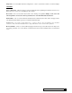
The bypass valve connects directly to the backplate of the valve with a pair of couplings and screws (Figure 4). To
facilitate this connection, remove the plate by pulling up on the u-clip on the back of the valve. Lubricate all o-rings
with silicone lubricant.
BYPASS VALVE INSTALLATION
SOFT-MINDER
®
METER ONLY
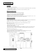
The Soft-Minder meter is placed between the bypass valve and the control in place of the couplings shipped with
the Cul-Flo-Valv
®
(Figure 5). Make sure the meter is on the outlet port of the control and that it is installed with the
arrow pointing in the direction of water flow. A pair of elongated bolts are packaged with the meter to hold the
bypass valve to the back plate of the control. Lubricate all o-rings with silicone lubricant.
SWEAT ADAPTOR INSTALLATION
The sweat adaptors use a snap ring to hold them to the backplate of the control valve. The back plate will need to
be removed from the valve for this connection. A pair of snap ring pliers, PN 00-5916-09, are needed for this
connection.
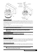
CAUTION: When reinstalling back plate to control valve, make sure the u-clip
fully engages the two bottom holes of the bracket (Figure 6). Secure bracket from
the top with the two mounting screws provided.