Cybex 600H Hiker Service Manual Cardiovascular Systems
The 600H Service Manual The 600H measures, monitors, and motivates your fitness and health. SM-15649 Rev A Cybex International, Inc.
PREFACE Read all instructions before using. Save These Instructions. ! WARNING: SERIOUS INJURY COULD OCCUR IF THESE PRECAUTIONS ARE NOT OBSERVED DO obtain a medical exam before beginning any exercise program. DO keep children away from the Hiker. Teenagers and disabled persons must be supervised while using. DO set up and operate the Hiker on a solid, level surface. DO NOT operate in recessed areas or on plush carpet. DO provide adequate clearance to the side, front, and back of Hiker.
TABLE OF CONTENTS 1 INTRODUCING THE 600H HIKER BY CYBEX Ergonomic Design Warranty Customer Service Hotline 3 3 4 2 DISASSEMBLY Setup and Assembly Choosing and Preparing a Site Step 1 Removing the Shrouds Step 2 Releasing Tension from the Linkage System Step 3 Removing the Linkage System Step 4 Disassembling the Tie Rod Assemblies Component Parts of the Linkage System Step 6 Removing the Pulley Assembly and Drive Belt Step 7 Removing the Foot Plate Step 8 Removing the Rear Pivot Arm Assembly Step 9 Removin
1 / INTRODUCING THE 600H HIKER BY CYBEX 600H Hiker™ by Cybex® 2
1 / INTRODUCING THE 600H HIKER BY CYBEX The 600H Hiker by Cybex is a revolutionary new product which defines a new exercise category. It is designed to provide the commercial fitness facility and personal user with an effective tool for total body conditioning. It utilizes a natural movement and provides training variety with its intuitive display control and feedback. It is the first and only product of its kind.
1 / INTRODUCING THE 600H HIKER BY CYBEX 600H features include: • Balanced total body involvement for a better cardiovascular workout. • “Free-stride” motion lets users determine the most comfortable stride length. • Contact heart-rate monitor lets users gauge the overall intensity of their workout. • Natural path of motion provides balanced conditioning to the lower body. • Fluid motion of handles helps upper body work efficiently. • Self-powered unit can be placed anywhere with no wires to trip over.
2 / DISASSEMBLY Set up and Assembly Setting up the 600H Hiker by Cybex is straightforward. Before you unpack the machine, however, be sure to select a suitable site. Choosing and Preparing a Site Fig. 2-1 The area that you select for your 600H Hiker should be well-lit and well-ventilated. Locate the 600H Hiker on a structurally sound and level surface (do not place in recessed areas or on plush carpet) a few feet from walls and other equipment. Allow for safe access and passage during use of the machine.
2 / DISASSEMBLY 3. Push the foot pedal backward with your foot (see figure 2-3) until you can rotate the long tie rod assembly freely with your hand. 4. Hold the foot pedal in this position and remove the 1/2-13 x 1.50” long screw. (See figure 2-2.) 5. Lay the long tie rod on the assembly floor. 6. Slowly and carefully, let the foot pedal come forward until there is no force on the pedal. STEP 3—Removing the Linkage System Must complete at least Step 2-Disassembly.
2 / DISASSEMBLY 14 9 Component Parts of the Linkage System 1. 1/2-13 x 1.75” long hex head bolt 2. 1/2-13 x 2.00” long hex head screw 3. 1/2-13 x 1.50” long BHC screw 11 4. 1/2-13 lock nut 5. 1/2-28 nut, left hand thread 6. 1/2-28 nut, right hand thread 10 7. 1/2” rod end with 1/2-28 left hand thread 8. 1/2” rod end with 1/2-28 right hand thread Fig. 2-6 9. Short tie rod 10. Long tie rod 11. Foot plate tie rod 12. 1/2” flat washer 13. 1/2” ID spacer 14. 3/4” ID wear washer x 7 15.
2 / DISASSEMBLY WARNING: Be sure that tension from the linkage system has been released prior to further disassembly. STEP 6-Removing the Pulley Assembly and Drive Belt Must complete at least Steps 1,2-Disassembly. (Tools required–One 1/8” Allen wrench, one 1/4” Allen wrench, one 9/16” wrench.) 1. Grasp the tension spring and pull down. (See figures 2-8 and 2-9.) Then slip the loop off of the spring shaft. Fig. 2-9 2. Remove two 1/4” set screws from each of the belt retainers at foot plate. 3.
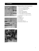
2 / DISASSEMBLY STEP 8-Removing the Rear Pivot Arm Assembly Must complete at least Steps 2 and 7-Disassembly (Tools required–One flat head screwdriver, two 1/2” wrenches.) 1. Remove both protective plastic caps. 2. Remove four 5/16 x .75” long screws and four 5/16 x .75” locks nuts. 3. Slide off plastic cap brackets. 4. Slide off both bearing sets. 5. Rotate pivot arm assembly to remove. Fig. 2-13 WARNING: Be sure that tension from the linkage system has been released prior to further disassembly.
2 / DISASSEMBLY STEP 10-Removing the Front Linkage Assembly Must complete Steps 1,2,3,4-Disassembly. (Tools required–One 9/16 deep socket, one 9/16 wrench.) 1. Remove one 3/8-16 x 3.75” long bolt and one 3/8-16 lock nut. (See figure 2-17.) 2. Slide out the front linkage assembly. (See figure 2-18.) NOTE: It is sometimes easier to see if you stand machine on its rear legs. Fig. 2-17 Fig. 2-18 10 WARNING: Be sure that tension from the linkage system has been released prior to further disassembly.
3 / INSTALLATION Installation of the 600H Hiker by Cybex can be unsafe if you don’t follow directions. The following installation steps are listed in sequential order assuming that the Hiker has been completely disassembled. NOTE: Safety glasses should be worn while assembling or disassembling the Linkage System. STEP 1-Installing the Front Linkage Assembly (Tools required–One 9/16” deep socket, on 9/16” wrench, safety glasses.) Fig. 3-1 1. Select one front linkage assembly: One 3/8-16 x 3.
3 / INSTALLATION 4. Slide the four 5/16-18 x .75” long screws through the holes in the flangette and mounting bracket. 5. Attach the four 5/16-18 lock nuts and tighten them snugly. (See figure 3-5.) 6. Adjust the position of the front pivot arm assembly by positioning the bumper against the flat of the 2 x 2” tube while making sure that the pivot arm assembly is perpendicular to the front tube. (See figure 3-6.) 7. Tighten the four 5/16-18 lock nuts to 15 ft-lb minimum. (See figure 3-5.) Fig.
3 / INSTALLATION STEP 4-Installing the Short Linkage Rod Assembly (Tools required–Two 3/4” wrenches.) 1. Select one short rod end assembly along with two 1/2-13 x 1.75” long bolts, and two 1/2-13 lock nuts. (See figure 3-10.) 2. Orient the linkage rod assembly so that the left hand threaded parts are facing the front end of the unit. (See figure 3-10.) 3. Slide the short linkage rod assembly into the front linkage assembly. (See figure 3-11.) Fig. 3-10 4. Slide from the top one 1/2-13 x 1.
3 / INSTALLATION STEP 5-Installing the Rear Pivot Arm Assembly (Tools required–Two 1/2” wrenches.) 1. Select one rear pivot arm along with four 1/16-18 x .75” long screws, four 5/16-18 lock nuts, two plastic cap brackets, four flangettes, and two 1” ID bearings. (See figure 3-13.) 2. Rotate the pivot arm assembly into position. To do so, put one pivot shaft of pivot arm through on pivot bracket, then twist and rotate the shaft until it fits into the other pivot bracket.
3 / INSTALLATION STEP 6-Assembling the Foot Plate Linkage Rod (No tools required.) 1. Select one foot plate linkage along with one 1/2-28 check nut (right hand thread) and one 1/2” rod end with 1/2-28 right hand thread. (See figure 3-19). 2. Screw the 1/2-28 lock nut into the foot plate linkage rod. 3. Screw the rod end with nut into the foot plate linkage rod. 4. Adjust the rod end with nut into the foot plate linkage rod. Fig. 3-18 5. Rotate the lock nut up to the tie rod end, but do not tighten.
3 / INSTALLATION STEP 8-Installing the Foot Plate Linkage Rod Assembly A (Tools required–One flat head screwdriver, one 3/4” wrench and one 5/16” Allen wrench.) 1. Select one foot plate linkage rod assembly along with 1/213 x 1.50” long bolt, five 3/4” ID wear washers (A), and one retainer. (See figure 3-23.) Fig. 3-23 2. Slide the pivot shaft of the foot plate linkage rod assembly through the foot plate from the outside of the unit. (See figure 3-23.) 3.
3 / INSTALLATION STEP 9-Assembling the Pulley Assembly (Tools required–Two 9/16” wrenches and one 1/4” Allen wrench.) 1. Select one pulley along with one pulley bracket, one extension spring, one 3/8-16 x 2.5” long bolt, two 3/8-16 lock nuts, two spring bracket bushings, one stepped spring bracket bushing, one pivot bushing, one spring alignment plate, and one 1/2 x 1.750” long shoulder belt. (See figure 327.) 2. Slide the pulley into the pulley bracket. 3. Slide one 3/8-16 x 2.
3 / INSTALLATION STEP 10-Installing the Pulley Assembly (Tools required–One 1/4” Allen wrench and one 9/16” wrench.) 1. Select one pulley assembly along with one 3/8-16 lock nut, two spring bracket bushings, and one 1/2 x .625” long shoulder bolt. 2. Slide two spring bracket bushings into the spring alignment bracket on the pulley assembly. (See figure 3-29.) Fig. 3-29 3. Position the pulley assembly against the mounting bracket onto the frame. Orient it in such a way that the head of the 3/8-16 x 2.
3 / INSTALLATION STEP 12-Installing the Belt Drive (Tools required–One 1/8” Allen wrench.) 1. Select one belt retainer and two 1/4 x 5/16” long set screws. 2. Route the drive belt over the drive pulley to its corresponding side. 3. Twist the drive belt 90 degrees so that the flat surface of the belt will engage the surface of the idler pulley. (See figure 333.) 4. Route the drive belt around the pulley. (See figure 3-33.) Fig. 3-33 5.
3 / INSTALLATION STEP 14-Assembling the Long Linkage Rod Assembly (Tools required–One 5/8” wrench and one 3/4” wrench.) Fig. 3-37 1. Select: one long tie rod along with one 1/2-28 check nut (left hand thread), one 1/2” rod end with 1/2-28 left hand thread, one 1/2-28 check nut (right hand thread, and one 1/2” rod end with 1/2-28 right hand thread. (See figure 3-37.) 2. Screw the 1/2-28 check nut (left hand thread) onto the 1/2-28 rod end with 1/2-28 left hand thread. 3.
3 / INSTALLATION STEP 15-Installing the Long Linkage Rod Assembly (Tools required–Two 3/4” wrenches and one 9/16” Allen wrench.) 1. Select one long linkage rod assembly along with one 1/2-13 x 2.00” long bolt, one 1/2-13 x 1.50” long bolt, two 1/2-13 lock nuts, and one 1/2” ID spacer. (See figure 3-39.) 2. Orient the linkage rod assembly so the the left hand threaded parts are facing toward the front of the unit. (See figure 3-40.) Fig. 3-41 3.
3 / INSTALLATION STEP 16-Adjusting the Linkage System (Tools required–One tape measure or scale, one 3/4” wrench one 5/8” wrench and a torque wrench.) 1. Align the front linkage assembly (as shown in figure 2-18) parallel to the frame. (See figure 3-45.) front linkage arm assembly Fig. 3-45 2. With the front linkage assembly parallel to the frame, verify that the foot plates are level with one another and are between 7.50” and 7.75” to the center line of the pivot shaft of the foot pedal from the floor.
3 / INSTALLATION STEP 17-Adjusting the End of the Stroke (Tools required–One tape measure and one 9/16” wrench.) 1. Rotate the rear pivot arm upward until the 1” diameter protrusion is 1.25” from making contact with the frame. (See figure 3-49.) 2. While holding the rear pivot arm in this position, adjust the stop so that it touches the 2 x 2” tube. (See figure 3-50.) 3. Tighten the check nut to a 22 ft-lb minimum. 4.
3 / INSTALLATION STEP 18-Attaching the Shrouds (Tools required–One Phillips head screwdriver.) 1. Select two 10-32 x .50” long screws, one left side shroud, one right side shroud, and one center shroud. 2. Push one foot plate to the bottom of the stroke. 3. Slide the center shroud into position. 4. Slide the left shroud down over the left handle and into position. 5. Slide the right shroud down over the right handle and into position. 6. Attach all 15 metal screws and washers to the shrouds and tighten.
4 / RETRO-KIT INSTALLATION 600H Hiker Retro-Kit (LT-15103) Installation Instructions (Tools required–1/8" Allen wrench, 5/32" Allen wrench, 9/16" socket/wrench, 9/16" open/box wrench.) Extract Calibration Settings Before changing the console board, extract calibration settings as follows: NOTE: If Hiker cannot be started due to a dead battery, this problem must first be resolved before continuing on. 1. Start stepping and press START. 2. Press the + and - keys in the INTENSITY window (at the same time).
4 / RETRO-KIT INSTALLATION NOTE: When starting a test stepping may help prevent battery drainage. You can enter the tests without stepping first. However, do not step while entering Static Diagnostic Check. Error 3 After installing this kit an initialization sequence is required. This will be noted by ERR 3 appearing on the display when START is first pressed. Follow the steps below to enter an initialization sequence. 1. Start stepping and press START. 2. Note ERR 3. 3.
4 / RETRO-KIT INSTALLATION there is no tension on the pedal. 5. Flip the hiker up onto the rear legs so the front of the unit is facing up to gain access to the underside of the shroud. 6. Remove the tension spring by grasping the tension spring and pulling downward until the Spring can be removed from the spring shaft. See figure 5-1. 7. Using a 9/16" wrench and socket, loosen and remove the nut and bolt that fasten the pulley to the bracket. Remove the pulley from the bracket. 8.
5 / DIAGNOSTICS Enter Diagnostic Mode To enter diagnostic mode, get on the Hiker and begin stepping. Press the START button and the display will light up. On the window labeled INTENSITY press the + and - keys at the same time. The display will briefly show the EPROM revision level and then go to Display LED testing mode. Display LED Test Press FAT BURN 1 to enter this test mode. Watch for any missing segments and verify that all digits and lights have uniform brightness.
5 / DIAGNOSTICS drop during startup, but within 15 seconds of start it should begin rising. 3. If the charger is working properly, a slow but steady rise of voltage will still be observed from 30 seconds to 1 minute, and usually beyond. Static Diagnostic Check This test employs the internal battery voltage measurement.
6 / PARTS LIST ITEM 1 2 3 4 5 6 7 8 9 10 11 12 13 14 15 16 17 18 19 20 21 22 23 24 25 26 27 28 29 30 31 32 33 34 35 36 37 38 39 40 41 42 43 44 45 46 47 48 49 50 51 52 53 54 55 56 57 58 59 30 QTY. 1 1 1 1 1 1 1 1 1 1 1 1 2 1 1 1 1 1 2 5 2 4 16 6 2 2 2 8 4 6 4 4 2 4 6 2 5 8 4 3 4 2 2 1 6 1 1 1 4 1 1 1 1 8 2 18 1 1 2 PART NO.
32 30 30 42 12 32 28 28 53 10 3 1 27 46 88 87 40 38 28 36 34 23 41 24 70 37 24 32 82 74 25 8 40 69 63 59 86 62 57 82 59 37 62 61 30 29 28 73 28 93 23 56 3 72 33 2 97 20 13 43 66 37 29 11 34 25 26 31 44 60 32 23 72 18 76 21 62 55 99 56 85 30 17 37 15 19 84 77 80 79 80 58 28 42 24 21 20 81 83 20 13 75 62 30 26 65 16 84 78 67 64 91 92 56 68 71 38 65 83 45 23 5 35 54 52 72 23 93 39 94 64 33 29 20 83 23 31
A C B D 3900-348 WIRE HARNESS, DISPLAY, UPRIGHT AC LINE VOLTAGE + BIOSIG H/R 6 5 11 4 8 9 TTL CAL 10 TIME REM.
10 Trotter Drive Medway, MA 02053 • 1-888-GO-CYBEX • 1-888-462-9239 • FAX 508-533-5183 • www.eCybex.com • techhelp@cybexintl.com Copyright © 2000, Cybex International, Inc.