
Service manual

15
3 / INSTALLATION
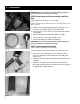
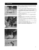
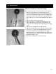
STEP 6-Assembling the Foot Plate Linkage Rod
(No tools required.)
1. Select one foot plate linkage along with one 1/2-28 check
nut (right hand thread) and one 1/2” rod end with 1/2-28 right
hand thread. (See figure 3-19).
2. Screw the 1/2-28 lock nut into the foot plate linkage rod.
3. Screw the rod end with nut into the foot plate linkage rod.
4. Adjust the rod end with nut into the foot plate linkage rod.
5. Rotate the lock nut up to the tie rod end, but do not tighten.
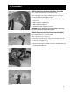
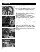
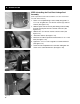
STEP 7-Attaching a Foot plate to the Front Pivot
Arm Assembly
(Tools required–One flat head screwdriver.)
1. Select a foot plate along with three 3/4” ID wear washers,
one belt attachment assembly and two retaining rings.
2. Slide one 3/4” ID wear washer (A) onto the pivot shaft. (See
figure 3-21.)
3. Slide one foot plate halfway onto the pivot shaft. (See figure
3-21.)
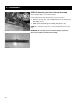
4. Slide one 3/4” ID wear washer onto the pivot shaft. (See
figure 3-21.)
5. Slide one belt attachment assembly (B) onto the pivot shaft.
(See figure 3-21.)
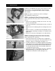
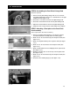
6. Slide the foot plate the rest of the way onto the pivot shaft.
(See figure 3-22.)
7. Slide one 3/4” ID wear washer (A) onto the pivot shaft. (See
figure 3-22.)
8. Attach the two retaining rings (C). (See figure 3-22).
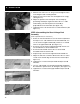
Fig. 3-18
Fig. 3-20
Fig. 3-19
Fig. 3-21
Fig. 3-22
CC
A
A
B