PU-8H8HBTE 8 x 8 HDMI HDBaseT™ Matrix (5-Play including LAN serving) OPERATION MANUAL
DISCLAIMERS The information in this manual has been carefully checked and is believed to be accurate. CYP (UK) Ltd assumes no responsibility for any infringements of patents or other rights of third parties which may result from its use. CYP (UK) Ltd assumes no responsibility for any inaccuracies that may be contained in this document. CYP (UK) Ltd also makes no commitment to update or to keep current the information contained in this document.
SAFETY PRECAUTIONS Please read all instructions before attempting to unpack, install or operate this equipment and before connecting the power supply. Please keep the following in mind as you unpack and install this equipment: • Always follow basic safety precautions to reduce the risk of fire, electrical shock and injury to persons. • To prevent fire or shock hazard, do not expose the unit to rain, moisture or install this product near water. • Never spill liquid of any kind on or into this product.
CONTENTS 1. Introduction �������������������������������������������1 2. Applications �������������������������������������������1 3. Package Contents ����������������������������������1 4. System Requirements ���������������������������2 5. Features ��������������������������������������������������2 6. Operation Controls and Functions �������3 6.1 Front Panel ��������������������������������������������������� 3 6.2 Rear Panel ����������������������������������������������������� 4 6.
1. INTRODUCTION s the Flagship 8x8 HDBaseT™ Matrix, the PU-8H8HBTE solution offers A complete HDBaseT™ 5-Play convergence. Installers can switch and distribute up to 8 HDMI sources, LAN (Local Area Network), 2-Way IR, and PoE (Power over Ethernet) to lengths of up to 100m using CAT5e/6 cable infrastructure. Control of the matrix is via IP control, RS-232, IR remote, or manual selection buttons. This single box solution will enable an installer to confidently integrate an eight zone multi-room AV system.
4. SYSTEM REQUIREMENTS • HDMI equipped source devices, connect with HDMI cables or DVI equipped source, connect with DVI to HDMI cables • HDMI equipped displays (TVs or monitors) or HDMI equipped AV receivers, connect with HDMI cables • Industry standard CAT5e/6/7 cables • HDBaseT™ Receivers (i.e. PU-506RX, PU-507RX or PU-1109RX) 5. FEATURES • • • Supports all v1.3 HDMI resolutions Supports uncompressed video/audio up to 10.
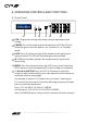
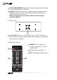
6. OPERATION CONTROLS AND FUNCTIONS 6.1 Front Panel MENU POWER 1 2 A 1 B 2 C 3 D 4 OUT E 5 F 6 G 7 H 8 IN LOCK 3 4 5 6 1 LCM : Displays the setting information of each input and output setting. 2 POWER: Press this button to power the device on/off. The LED will illuminate green when the power is on, red when it is in 'Standby' mode. 3 LOCK: Press this button to lock all the buttons on the panel; press again to unlock. The LED will illuminate green when locked.
6.
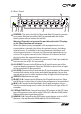
DC 24V MAIN POWER: Plug the 24 V DC power supply into the unit and connect the adaptor to an AC outlet. 11 PoE 24V: Plug the 24 V PoE power supply into the unit and connect the adaptor to an AC outlet. This unit will mainly power PoE (Power over Ethernet) capaable receiver units. Warning: Please do not connect the CAT5e/6/7 cable into the receiver's LAN port. 6.3 Side Panel 1 1 Fan Ventilator: These are air ventilation areas, DO NOT block these areas or cover it with any object.
6.
6.
6.7 RS-232 and Telnet Commands Command Description A1~A8 Switch Output A to 1~8 B1~B8 Switch Output B to 1~8 C1~C8 Switch Output C to 1~8 D1~D8 Switch Output D to 1~8 E1~E8 Switch Output E to 1~8 F1~F8 Switch Output F to 1~8 G1~G8 Switch Output G to 1~8 H1~H8 Switch Output H to 1~8 ABCE…1~ABCD…8 Switch Output ABCD… to 1~8 at the same time SETIP Setting IP. SubNet.
6.8 Telnet Control Before attempting to use the telnet control, please ensure that both the Matrix (via the 'LAN /CONTROL' port) and the PC/Laptop are connected to active networks. Note: Please do not connect both the Matrix and the PC/Laptop with a single CAT5e/6 cable as it will not access the telnet function. To access the telnet control in Windows 7, click on the 'Start' menu and type "cmd" in the Search field then press enter.
Once in the command line interface (CLI) type "telnet", a space, then the IP address of the unit you wish to control, a space and "23", then hit enter. Note: The IP address of the Matrix can be displayed on the device's LCM monitor by pressing the Menu button twice. This will bring us into the device which we wish to control. Type "HELP" to list the available commands. Type “IPCONFIG” To show all IP configurations.
6.9 Web GUI Control On a PC/Laptop that is connected to an active network, open a web browser and type the Matrix's IP address on the web address entry bar. The browser will display the device's status, control and User setting pages. Click on the 'Control' tab to control power, input/output ports, EDID and reset mode.
Click on the 'User Setting' tab allows you to reset the IP configuration. The system will ask for a reboot of the device every time any of the settings are changed. The IP address needed to access the Web GUI control will also need to be changed accordingly on the web address entry bar.
7. CONNECTION DIAGRAM ZONE A RX Power ZONE B RX Link IR 2 IR 1 Extender Blaster RS232 Out CAT5e/6 In Power ZONE C Link IR 2 IR 1 Extender Blaster RS232 Out CAT5e/6 In RX Power RX Link IR 2 IR 1 Extender Blaster RS232 Out ZO ZONE D CAT5e/6 In Power RX Link IR 2 IR 1 Extender Blaster RS232 Out CAT5e/6 In Power Ex IR In (ALL) ALL Wireless Router with Internet connection RS-232 Equipped PC or Notebook 1.
ONE E ZONE H HDMI Outputs IR Out/In RX Link RS232 Out CAT5e/6 In Power Link IR 2 IR 1 Extender Blaster RS232 Out CAT5e/6 In RX Power Link IR 2 IR 1 Extender Blaster RS232 Out CAT5e/6 In RX Power Link IR 2 IR 1 Extender Blaster RS232 Out CAT5e/6 In Receiver Units Single CAT 5e/6 Cable Model Shown: HDBaseT 8×8 HDMI Matrix over CAT5e/6/7 V+ IR OUT OUT 6 ZONE G Displays IR 2 IR 1 xtender Blaster N ZONE F G IR OUT CAT5e/6 OUT IR IN H GND CAT5e/6 OUT GND 3 4 1 2 V+ GND P
8. SPECIFICATIONS Video Bandwidth 255 MHz/6.75 Gbps Input Ports 8×HDMI , 9×IR Extender, 1×RS-232, 1×LAN, 1×Mini USB-B type(for firmware update only) Output Ports 8×CAT5e/6/7, 9×IR Blaster ESD Protection Human-body Model: ± 8kV (Air-gap discharge) ± 4kV (Contact discharge) Power Supply 24 V/6.
9.
CYP (UK) Ltd., Unit 7, Shepperton Business Park, Govett Avenue, Shepperton, Middlesex, TW17 8BA Tel: +44 (0) 20 3137 9180 | Fax: +44 (0) 20 3137 6279 Email: sales@cypeurope.com www.cypeurope.