
Specifications


3
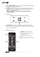
6. OPERATION CONTROLS AND FUNCTIONS
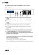
6.1 Front Panel
POWER LOCK
MENU OUTA
1
B
2
C
3
D
4
IN
E
5
F
6
G
7
H
8
2 3 4 5 61
1
LCM : Displays the setting information of each input and output
setting.
2
POWER: Press this button to power the device on/o. The LED will
illuminate green when the power is on, red when it is in 'Standby'
mode.
3
LOCK: Press this button to lock all the buttons on the panel; press
again to unlock. The LED will illuminate green when locked.
4
IR: IR Receiver window (accepts the remote control signal of this
device only).
5
MENU: Press this button to access the LCM menu system, from here
EDID settings can be managed and IP system settings are displayed.
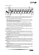
6
1~8/A~H and OUT/IN: Press the OUT or IN button to select the
output or input mode and then press the required number button to
make the selection accordingly.
For example, if outputs A~D need to be set to input 1 and outputs
E~H need to be set to input 2, then the following sequence of button
presses need to be performed:
Press: OUT
A
B
C
D
IN
1
MENU,
and then press: OUT
E
F
G
H
IN
2
MENU.
Note: If the MENU button is not pressed the selection will not be changed.