
Low Voltage Microcontroller Specification Sheet

CY7C601xx, CY7C602xx
Document 38-16016 Rev. *E Page 50 of 68
‘
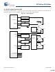
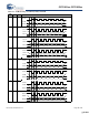
18.1.3 Programmable Interval Timer
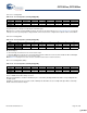
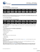
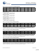
Table 18-8. Timer Capture 1 Falling (TCAP1F) [0x25] [R/W]
Bit # 7 6 5 4 3 2 1 0
Field Capture 1 Falling [7:0]
Read/Write R R R R RRR R
Default 0 0 0 0 000 0
Bit [7:0]: Capture 1 Falling [7:0]
This register holds the value of the free running timer when the last falling edge occurred on the TIO1 input. The bits stored here
are selected by the Prescale [2:0] bits in the Timer Configuration register. When capture 0 is in 16-bit mode this register holds
the high order eight bits of the 16-bit timer from the last TIO0 falling edge.
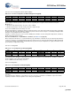
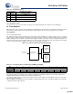
Table 18-9. Capture Interrupt Status (TCAPINTS) [0x2C] [R/W]
Bit # 7 6 5 4 3 2 1 0
Field Reserved Cap1 Fall
Active
Cap1 Rise
Active
Cap0 Fall
Active
Cap0 Rise
Active
Read/Write ––––R/W R/W R/W R/W
Default 0 0 0 0 000 0
These four bits contains the status bits for the four timer captures for the four timer block capture interrupt sources. Writing any
of these bits with 1 clears that interrupt.
Bit [7:4]: Reserved
Bit 3: Cap1 Fall Active
0 = No event
1 = A falling edge has occurred on TIO1
Bit 2: Cap1 Rise Active
0 = No event
1 = A rising edge has occurred on TIO1
Bit 1: Cap0 Fall Active
0 = No event
1 = A falling edge has occurred on TIO0
Bit 0: Cap0 Rise Active
0 = No event
1 = A rising edge has occurred on TIO0
Note The interrupt status bits are cleared by firmware to enable subsequent interrupts. This is achieved by writing a ‘1’ to the
corresponding Interrupt status bit.
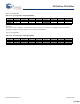
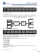
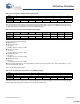
Table 18-10. Programmable Interval Timer Low (PITMRL) [0x26] [R]
Bit # 7 6 5 4 3 2 1 0
Field Prog Interval Timer [7:0]
Read/Write R R R R RRR R
Default 0 0 0 0 000 0
Bit [7:0]: Prog Interval Timer [7:0]
This register holds the low order byte of the 12-bit programmable interval timer. Reading this register moves the high order byte
into a holding register allowing an automatic read of all 12 bits simultaneously.
[+] Feedback [+] Feedback