D-Link DI-624S High-Speed 2.4 GHz Wireless Storage Router Manual Building Networks for People Ver 1.
Contents Package Contents ........................................................................................................... 3 Introduction ..................................................................................................................... 4 Connections .................................................................................................................... 5 LEDs ...........................................................................................................
Advanced > Firewall .................................................................................................. 44 Advanced > DMZ ....................................................................................................... 45 Advanced > DDNS..................................................................................................... 46 Advanced > Printer .................................................................................................... 47 Advanced > QoS...........
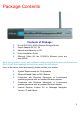
Package Contents • • • • • Contents of Package: D-Link DI-624S 2.4GHz Wireless Storage Router Power Adapter-DC 5V, 3A Manual and Warranty on CD Quick Installation Guide Ethernet Cable (All the DI-624S’s Ethernet ports are Auto-MDIX) Note: Using a power supply with a different voltage rating than the one included with the DI-624S will cause damage and void the warranty for this product. If any of the above items are missing, please contact your reseller.
Introduction The D-Link DI-624S Wireless Storage Router is an 802.11b/g high-performance, wireless router that supports high-speed wireless networking at home, at work or in public places. Unlike most routers, the DI-624S provides data transfers at up to 8X (compared to the standard 11 Mbps) when used with other D-Link products. The 802.11g standard is backwards compatible with 802.11b products. This means that you do not need to change your entire network to maintain connectivity.
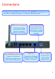
Connections All Ethernet Ports (WAN and LAN) are auto MDI/MDIX, meaning you can use either a straight-through or a crossover Ethernet cable. USB 2.0 Connections. Factory Reset Button Use these ports to connect your USB printer or memory media for file sharing. Pressing this button will restore the router to its factory default settings. Auto MDI/MDIX LAN Ports WAN Port Power Adapter Connect the Ethernet cable from computers on your LAN to these ports.
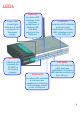
LEDs WAN LED Power LED A solid light indicates a valid connection to the power supply. An active LED indicates a link has been established. A blinking LED indicates activity on the WAN port. USB LED An active LED indicates a link has been established. A blinking LED indicates activity on the USB port. Status LED LAN LEDs A blinking LED indicates the DI-624S is functioning properly. WLAN LED An active LED indicates a link has been established. A blinking LED indicates activity on the LAN port.
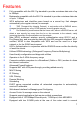
Features • • • Fully compatible with the 802.11g standard to provide a wireless data rate of up to 54Mbps Backwards compatible with the 802.
• • • • • • • • various devices to be shared over a network, such as USB storage devices and printers VPN Pass Through DMZ and DDNS functions Stateful Packet Inspection for protection against unwanted packets Quality of Service (QoS) for prioritizing ports and IP addresses UPnP AV function for sharing audio and video files using a media storage device Multiple users and administrators with configurable privileges for each Intrusion detection for ICMP, SYN, UDP flood, Land, IP spoof, Ping of Death, Port Sca
Wireless Basics D-Link wireless products are based on industry standards to provide easy-to-use and compatible high-speed wireless connectivity within your home, business or public access wireless networks. D-Link wireless products will allow you access to the data you want, when and where you want it. You will be able to enjoy the freedom that wireless networking brings. A WLAN is a cellular computer network that transmits and receives data with radio signals instead of wires.
Wireless Basics (continued) Standards-Based Technology The DI-624S Wireless Broadband Router utilizes the new 802.11g standard. The IEEE 802.11g standard is an extension of the 802.11b standard. It increases the data rate up to 54 Mbps within the 2.4GHz band, utilizing OFDM technology. This means that in most environments, within the specified range of this device, you will be able to transfer large files quickly or even watch a movie in MPEG format over your network without noticeable delays.
Getting Started Setting up a Wireless Infrastructure Network Please remember that D-Link AirPlus G wireless devices are pre-configured to connect together, right out of the box, with their default settings. For a typical wireless setup at home (as shown above), please do the following: 1. You will need broadband Internet access (a Cable or DSL-subscriber line into your home or office) 2. Consult with your Cable or DSL provider for proper installation of the modem 3.
5. (See the printed Quick Installation Guide included with the network adapter.) 6. Install the D-Link DWL-G650 wireless Cardbus adapter into a laptop computer. (See the printed Quick Installation Guide included with the DWL-G650.) 7. Install the D-Link DFE-530TX+ adapter into a desktop computer. The four Ethernet LAN ports of the DI-624S are Auto MDI/MDIX and will work with both Straight-Through and Cross-Over cable. (See the printed Quick Installation Guide included with the DFE-530TX+.
Using the Configuration Wizard Whenever you want to configure your network or the DI-624S, you can access the Configuration Menu by opening the web-browser and typing in the IP Address of the DI-624S. The DI-624S default IP Address is shown to the right: • • • • • 192.168.0.1 Open the web browser Type in the IP Address of the Router (http://192.168.0.1) Type admin in the User Name field Leave the Password blank Click OK The Home > Wizard screen will appear.
Using the Configuration Menu (continued) Home > Wireless WCN WCN or Windows Connect Now Technology is used to automatically configure the wireless settings for this device. The WCN must be previously configured on computer running a Windows XP operating system, which has Service Pack 2 installed.
Wireless QoS (WMM) Clicking the Enabled radio button in this section will enable QoS for WiFi MultiMedia (WMM). This function will give priority to audio and video information travelling over the wirless network. This function is especially important in sharing files over your LAN using a media server, such as the D-Link Media Lounge and thus will help provide a continuous media stream. SSID Service Set Identifier (SSID) is the name designated for a specific wireless local area network (WLAN).
Open System/Shared Key The Open System/Shared Key choice for Authentication will produce the same screen for the user’s configuration. The Open System choice is for general use and utilizes the basic WEP encryption. The Shared Key choice is used between cooperating devices that share a common encryption key. WEP (Wireless Encryption Protocol or Wired Equivalent Privacy) encryption can be enabled for security and privacy.
WPA WPA or Wireless Protection Access is a new an improved standard of wireless security. WPA offers encryption keys of up to 256-bits that automatically change frequently. On this router, the WPA utilizes the RADIUS protocol, which utilizes a server to authorize the user by matching a Shared Secret password listed in its RADIUS database. There are two choices for the user to choose from. WPA and WPA2 which uses the Advanced Encryption Standard (AES).
Using the Configuration Menu (continued) Home > WAN Static IP Address Choose Static IP Address if all WAN IP information is provided to you by your ISP. You will need to enter in the IP address, subnet mask, gateway address, and DNS address(es) provided to you by your ISP. Each IP address entered in the fields must be in the appropriate IP form, which are four octets separated by a dot (x.x.x.x). The Router will not accept the IP address if it is not in this format.
Using the Configuration Menu (continued) Dynamic IP Address Dynamic Choose Dynamic IP Address to obtain IP address information automatically from your ISP. This option should be selected if your ISP has not supplied you with an IP address. This option is commonly used for Cable modem services. Host Name The Host Name is optional but may be required by some ISPs. The default host name is the device name of the Router and may be changed.
Using the Configuration Menu (continued) Home > WAN > PPPoE Choose PPPoE (Point to Point Protocol over Ethernet) if your ISP uses a PPPoE connection. Your ISP will provide you with a username and password. This option is typically used for DSL services. Select Dynamic PPPoE to obtain an IP address automatically for your PPPoE connection. Select Static PPPoE to use a static IP address for your PPPoE connection. PPPoE Choose this option if your ISP uses PPPoE. (Most DSL users will select this option.
Clone MAC Address Primary DNS Address Secondary DNS Address The default MAC address is set to the WAN’s physical interface MAC address on the Broadband Router. You can use the “Clone MAC Address” button to copy the MAC address of the Ethernet Card installed by your ISP and replace the WAN MAC address with the MAC address of the router. It is not recommended that you change the default MAC address unless required by your ISP.
Using the Configuration Menu (continued) Home > WAN > Others > PPTP PPTP or Point-to-Point Protocol is a safe method of sending information between VPN’s securely using encryption over PPP. You, as the client, need to enter the correct information that the server has in order to create that secure tunnel. Using Dynamic IP, the router will set your basic IP parameters for you, such as the IP Address, Subnet Mask and Gateway. For Static IP, this information must be set manually by the user.
Using the Configuration Menu (continued) Home > WAN > Others > L2TP Some ISPs may require the user to uplink using the Layer 2 Protocol Tunneling (L2PT) method. L2PT is a VPN protocol that will ensure a direct connection to the server using an authentication process that guarantees the data originated from the claimed sender and was not damaged or altered in transit. Once connected to the VPN tunnel, it seems to the user that the client computer is directly connected to the internal network.
Using the Configuration Menu (continued) Home > WAN > Others > BigPond Cable This selection is for users having Big Pond Cable as their ISP. Enter the following information, as provided to you by your ISP. User Name Enter the user name as provided to you by your ISP. Password Enter The PPPoE user name provided to you by your ISP. Retype Password Retype the password entered in the previous field. Auth Server Enter the name of the Authentication Server as provided to you by your ISP.
Using the Configuration Menu (continued) Home > LAN LAN is short for Local Area Network. This is considered your internal network. These are the IP settings of the LAN interface for the DI-624S and may be referred to as Private settings. You may change the LAN IP address if needed. The LAN IP address is private to your internal network and cannot be seen on the Internet. IP Address The IP address of the LAN interface. The default IP address is 192.168.0.1.
Using the Configuration Menu (continued) Home > DHCP Dynamic Host Configuration Protocol (DHCP) allows the gateway to automatically obtain the IP address from a DHCP server on the service provider’s network. The service provider assigns a global IP address from a pool of addresses available to the service provider. Typically the IP address assigned has a long lease time, so it will likely be the same address each time the Router requests an IP address.
Using the Configuration Menu (continued) Home > File Sharing The following window and explanation describes how to set up your DI-624S as a file-sharing server. Using Samba technology, the router will be able to share files between computers with little regard to the operating system in use on a computer that has been given access to this file sharing service. The file sharing service is implemented using either or both of the two USB ports at the back of the router.
Advanced > File Sharing > Server Setup The Server Setup window is used to configure the router to be a file-sharing device on the network. Server Setup Click the corresponding radio button if you wish to enable or disable the File Server function on the Router. Group Enter the name of the share group on the internal network with whom you wish to share files. Name Enter the name of the device to be used as the file sharing server. As shown in the window above, this should be the DI-624S.
User Name Enter the name of the user to be added to the user group. This name must be identical to the one the user will input when asked for authorization by the router. User Description Enter a description of the user to identify that person to the administrator. This is an optional field. Password / Confirm Password Enter the password used to authorize this user on the router, then confirm that password in the following field.
Select Directory Pop-Up Window This window will appear when the Select Directory button is clicked in the previous window. Using this window, the administrator can create directories for sharing on the network. To create a directory, enter a name of your choice in the Create Directory field and click Add. Once entered, it will appear in the window above. You may then click on the directory to enter it in the Select Directory and Delete Directory fields.
Using the Configuration Menu (continued) Home > FTP Utilizing the USB ports and an external file sharing system, you may use this device with the FTP protocol. FTP or File Transfer Protocol allows computer users running various operating systems to share files. This feature is very similar to the file sharing feature described in the previous section both in implementation and usage. The FTP service may be enabled for the WAN (external), LAN (internal) or both networks.
Using the Configuration Menu (continued) Home > Personal Web The Personal Web screen will allow the user to set up a web page for guests to use for accessing stored files on one of the router’s USB ports. In order for this to properly function, the administrator must have an HTML documents stored on a USB-connected memory device. Through this HTML page, guests can access files on the USB storage device, just as they could on an Internet WWW page.
User Name Enter the User Name you wish to allot this Personal Web page. This is the User Name, along with the Password in the next field, that will be required to access the Personal Web page on a USB storage device connected to the Router. Password Enter the Password you wish to allot this Personal Web page. This is the Password, along with the User Name in the previous field, that will be required to access the Personal Web page on a USB storage device connected to the Router.
Using the Configuration Menu (continued) Home > UPnP AV The UPnP (Universal Plug and Play) AV screen will allow the administrator to share audio and video files for viewing or listening over the network. These files, which would be stored on an external file-sharing device attached to one of the USB ports, can be added or adjusted by using the Select Directory Pop-up window previously described.
Using the Configuration Menu (continued) Advanced > Virtual Server To view the following window, click on the Advanced tab at the top of the window and then click the Virtual Server button to the left. The Virtual Server will allow remote users access to various services outside of their LAN through a public IP address, such as FTP (File Transfer Protocol) or HTTPS (Secure Web).
• • • • • • • • • SMTP – Simple Mail Transfer Protocol, used to transmit e-mail messages between parties POP3 – Post Office Protocol version 3, used to retrieve e-mail from a mail server Telnet – A terminal emulation program used for remote configuration IPSec – IP Security, used for a secure transfer of information over the network.
Using the Configuration Menu (continued) Advanced > Applications The Applications window is used to configure applications that require multiple connections, such as Internet Telephony, video conferencing and Internet gaming. The following window lists six Special Applications that commonly use more than one connection. To configure one of these applications, click its corresponding edit icon and then modify the fields listed below the following figure and then clicking the Enabled radio button.
Using the Configuration Menu (continued) Advanced > Filters Packet filtering is a basic security measure that should be used on any network that is exposed to a security risk. A packet filter system examines data packets and scrutinizes them in order to control network access. Filtering rules determine whether packets are passed through the Router from either side of the gateway. The rules are created and controlled by the network administrator and can be precisely defined.
Advanced > Filters > IP Filters This window will aid the use in configuring filters for IP addresses. This will deny specified LAN IP addresses or specific ports associated with these LAN IP address from accessing the Internet. Well known ports have already been previously set in the IP Filters List and can be modified by clicking their corresponding edit icon, and simple adding an IP address to the configuration.
Advanced > Filters > MAC Filters All computers are uniquely identified by their MAC (Media Access Control) address. The following window will allow users to deny computers access to the Internet or only allow certain computers access to the Internet, based on their MAC address. To access this screen, click the Advanced tab along the top of the configuration window, then the Filters tab to the left hand side and finally click the corresponding radio button for MAC Filters.
Using the Configuration Menu (continued) Advanced > Parental Control Parental Control is used to deny access to certain websites and domains on the Internet. This is beneficial for users who want to deny computers on the LAN entry to websites, especially for parents who want to guard against questionable content for their children’s computers. The administrator has two choices in this screen, URL blocking (websites) and Domain Blocking.
Advanced > Parental Control > URL Blocking URL or Uniform Resource Locator is a specially formatted text string that uniquely defines an Internet website. This window will allow users to block computers on the LAN from accessing certain URLs. This may be accomplished by simply entering the URL to be blocked in the URL Address field. The user may also use this field to block certain websites by entering a keyword into the URL Address field.
Advanced > Parental Control > Domain Blocking Domain blocking is a method of denying or allowing computers on the LAN access to specific domains on the Internet. There are two available methods available to the user to institute Domain blocking on the router. Under the Domain Blocking header in the screen pictured above, the user has three choices, one of which is to disable Domain blocking. The second choice is Allow users to access all domains except “Blocked Domains”.
Using the Configuration Menu (continued) Advanced > Firewall This Router comes equipped with a firewall. The Firewall configuration screen allows the Router to enforce specific predefined policies intended to protect against certain common types of attacks. To configure the Router’s firewall, click the Advanced tab at the top of the screen and then the Firewall tab to the left. To configure rules for the firewall, modify the following fields and click Apply to set the rule in the Routers memory.
Using the Configuration Menu (continued) Advanced > DMZ Firewalls may conflict with certain interactive applications such as video conferencing or playing Internet video games. For these applications, a firewall bypass can be set up using a DMZ IP address. The DMZ IP address is a “visible” address and does not benefit from the full protection of the firewall function. Therefore it is advisable that other security precautions be enabled to protect the other computers and devices on the LAN.
Using the Configuration Menu (continued) Advanced > DDNS The DI-624S supports DDNS or Dynamic Domain Name Service. Dynamic DNS allows a dynamic public IP address to be associated with a static host name in any of the many domains, allowing access to a specific host from various locations on the Internet. With this function enabled, remote access to a host will be allowed by choosing a URL by using the pull-down menu.
Using the Configuration Menu (continued) Advanced > Printer The DI-624S has a special ability to serve as a print server when using a USB printer. After connected to the printer through one of the USB ports at the rear of the router, the user must enable the router to act as a print server by clicking the Enabled radio button. Once enabled, the router should recognize the connected printer and establish it in the queue as lp1.
Using the Configuration Menu (continued) Advanced > QoS QoS or Quality of Service is used to allot bandwidth and priority from the router. To allot bandwidth per port on the router, click the QoS Bandwidth radio button and configure the parameters. QoS may be configured per Physical Port, MAC address, IP address or specified application. See the following explanation for more detailed information on each type of QoS setting.
Advanced > QoS > MAC The user may also set QoS by specific MAC address. To enable QoS per MAC address, first click the MAC radio button which will reveal the preceeding screen for the user to configure. Ensure that the Bandwidth configured does not exceed the incoming bandwidth from the ISP or it will cause other devices on the LAN to slow down due to decreased bandwidth. Check with your ISP for more information on the bandwidth allotted to your account.
Advanced > QoS > IP The user may also set QoS by specific IP address. To enable QoS per IP address, first click the IP radio button which will reveal the preceeding screen for the user to configure. Ensure that the bandwidth does not exceed the incoming bandwidth from the ISP or it will cause other devices on the LAN to slow down due to decreased bandwidth. Check with your ISP for more information on the bandwidth allotted to your account.
Advanced > QoS > Application The user may also set QoS by specific protocol. To enable QoS per protocol, first click the Application radio button which will reveal the preceeding screen for the user to configure. Ensure that the bandwidth does not exceed the incoming bandwidth from the ISP or it will cause other devices on the LAN to slow down due to decreased bandwidth. Check with your ISP for more information on the bandwidth allotted to your account.
Using the Configuration Menu (continued) Advanced > Performance The Performance window is used to configure settings for the Access Point feature of this device. Configuring these settings may increase the performance of your router but if you are not familiar with networking devices and protocols, this section should be left at its default settings. Below is a list of the functions associated with the Access Point feature of the router. Click Apply when you have completed your changes.
DTIM Interval DTIM (Delivery Traffic Indication Message) is a countdown informing clients of the next window for listening to broadcast and multicast messages. The default setting is 3. Preamble Type Select Short or Long Preamble. The Preamble defines the length of the CRC block (Cyclic Redundancy Check is a common technique for detecting data transmission errors) for communication between the wireless router and the roaming wireless network adapters.
Using the Configuration Menu (continued) Tools > Admin At this page, the DI-624S administrator can change the system password. There are two accounts that can access the Broadband Router’s Web-Management interface. They are admin and user. Admin has read/write access while user has read-only access. User can only view the settings but cannot make any changes. Administrator admin is the Administrator login name. Password Enter the password here and the same password in the Confirm Password field.
Using the Configuration Menu (continued) Tools > Time The system time is the time used by the DI-624S for scheduling services. You can manually set the time, connect to a NTP (Network Time Protocol) server or synchronize the time on the router with your PC. If an NTP server is set, you will only need to set the time zone and the update Interval. You may also set the time from the clock on your computer by checking the corresponding radio button.
Using the Configuration Menu (continued) Tools > System The System window has three basic functions for the DI-624S administrator. Configuration settings can be saved to a local hard drive on your computer by clicking the Save button. This will produce a new window from your operating system inquiring you about the location where you would like to save your files.
Using the Configuration Menu (continued) Tools > Firmware You can upgrade the firmware of the Router here. Make sure the firmware you want to use is on the local hard drive of the computer. Click on Browse to browse the local hard drive and locate the firmware to be used for the update. Please check the D-Link Support site for firmware updates at http://support.dlink.com. You can download firmware upgrades to your hard drive from the D-Link support site.
Using the Configuration Menu (continued) Tools > Misc. Ping Test The Ping Test is used to send Ping packets to test if a computer is on the Internet. Enter the IP Address that you wish to Ping, and click Ping. Block WAN Ping Discard Ping from WAN side- If you choose to block WAN Ping, the WAN IP Address of the DI-624S will not respond to pings. Blocking the Ping may provide some extra security from hackers. Click Enabled to block the WAN ping.
VPN Pass Through The DI-624S supports VPN (Virtual Private Network) pass-through for both PPTP (Point-to-Point Tunneling Protocol) and IPSec (IP Security). Once VPN pass-through is enabled, there is no need to open up virtual services. Multiple VPN connections can be made through the DI-624S. This is useful when you have many VPN clients on the LAN network. PPTP select Enabled or Disabled. IPSec select Enabled or Disabled.
Using the Configuration Menu (continued) Tools > Cable Test The above window is a Vitrual Cable Tester and it shows the user the current status of the ports of the Router. In this window, we can see that LAN4 port is connected at a speed of 100Mbps Full (duplex) and all the other connections do not have a valid link. Clicking the More Info button will open an additional window with more information about this connection, as shown below.
Using the Configuration Menu (continued) Status > Device Info This page displays the current information for the DI-624S. It will display the LAN, WAN, Wireless 802.11g and Disk Information statistics. If your WAN connection is set up for a Dynamic IP address then a Release button and a Renew button will be displayed. Use Release to disconnect from your ISP and use Renew to connect to your ISP. If your WAN connection is set up for PPPoE, a Connect button and a Disconnect button will be displayed.
Subnet Mask: WAN/Public Subnet Mask Default Gateway: WAN/Public Gateway IP Address Domain Name Server: WAN/Public DNS IP Address Wireless 802.
Using the Configuration Menu (continued) Status > Log The Router keeps a running log of events and activities occurring on the Router. If the device is rebooted, the logs are automatically cleared. You may save the log files under Log Settings.
Using the Configuration Menu (continued) Status > Statistics The screen above displays the Traffic Statistics. Here you can view the amount of packets that pass through the DI-624S on both the WAN and the LAN ports. The traffic counter will reset if the device is rebooted or can be reset by clicking the Reset button. To refresh current statistics, click the Refresh button.
Using the Configuration Menu (continued) Status > Wireless The wireless client table displays a list of current connected wireless clients. This table also displays the MAC address and mode of the connected wireless client. Click on Help at any time, for more information.
Using the Configuration Menu (continued) Status > Printer Info The Printer Info window displays a list of Printers that are using the DI-624S as a print server. These printers are defined by their Queue Name and Printer Name. The status of these printers is located to the right under the heading Printer Server Status.
Using the Configuration Menu (continued) Active Session The Active Session window allows users to view the packets passing through the router, whether from the source or to the destination. This window displays the total TCP and UDP packets in the NAPT Session section. This is a total of the Active Session section on the bottom of the screen. The Active Session section will sub-divide the NAPT session section into separate IP addresses and their TCP and UDP packets.
Sub-divided again, this window displays more detailed information on the TCP/UDP actions taken by the specific IP address, as stated below. Protocol Displays the protocol used by the corresponding IP address, whether it be TCP or UDP. Source IP Displays the IP address of the device sending information. Source Port Displays the virtual port used by the source IP address. Dest IP Displays the IP address of the destination of the packets sent from the Source IP.
Using the Configuration Menu (continued) Help The Help tab will give basic information referring to various screens locted in the Router. To view a specific section, click on its hyperlinked name. A new window of information will appear.
Technical Specifications Standards • • • • IEEE 802.11g IEEE 802.11b IEEE 802.3 IEEE 802.
Technical Specifications (continued) Safety and Emissions: • • EMI: FCC Class B, CE Class B, C-Tick , IC Safety: CSA International Wireless Frequency Range: LEDs: • 2.4GHz to 2.462GHz • • • • Power WAN LAN (10/100) WLAN (Wireless Connection) Status Physical Dimensions: • • • L = 7.56 inches (192mm) W = 4.65 inches (118mm) H = 1.22 inches (31 mm) Wireless Transmit Power: Security: • • 11g: 14dBm Typical 11b: 16dBm Typical • • • • 802.
Technical Specifications (continued) Warranty: • 3 year (depends on D-Link global warranty policy) Wireless Data Rates with Automatic Fallback: • • • • • • • • • • • • • 54 Mbps 48 Mbps 36 Mbps 24 Mbps 22 Mbps 18 Mbps 12 Mbps 11 Mbps 9 Mbps 6 Mbps 5.
Appendix WCN and the Wireless Setup Wizard WCN or Windows Connect Now technology has been recently incorporated by D-Link to quickly aid the user in setting up a secure wireless environment. Combining the new WCN technology incorporated by Windows and only available through a PC that has a wireless NIC card and is running the Windows XP Operating System with Service Pack 2 installed, the user will configure the wireless settings only once and then save it to a USB flash drive.
Choose “Set up a new wireless network”. Click Next. Enter a network name of up to 32 characters to identify your wireless network. This name will be common to all users on the wireless LAN. Choose “Manually assign a network key” which will be configured in the next window. Click Next. Choose a key that will be shared among users on your LAN. There are certain guidelines to choosing this key, as stated on the screen to the left. Confirm the network key by retyping it in the following field.
Insert the USB drive into a USB port on the computer, choose “Use a USB flash drive”. Click Next. The settings will the automatically be uploaded to your USB flash drive. Once saved the user is to unplug the device, in the proper method, and then plug that USB flash drive into all devices that will be accessing the wireless LAN. Each device will upload the configurations automatically and be instantly accessible on the wireless LAN.
Installing a Printer on your DI-624S The Di-624S can be used as a print server for devices on your LAN. Once you have installed the USB printer through the router, the user must set up the computer on the LAN for the printer as well. The following explanation will guide you through the steps needed to do this. Remember to enter the same Queue Name on the PC as your router displays or the printer will not function properly.
In the Local or Network Printer window, choose “Local printer attached to this computer”. Click Next. Then the user must choose the type of installation for the wizard. Choose “Create a new port” and use the pull-down menu to select “Standard TCP/IP Port”. Click Next. The next screen to appear is the “Welcome to the Add Standard TCP/IP Printer Port Wizard”. Make sure that the printer is turned on and the network is properly configured. Click Next.
Enter the IP address (default: 192.168.0.1) of the DI-624S to the “Printer Name or IP Address” field. In the Port Name field, be sure add a name to the router IP address to differentiate it from other devices.(ex: IP_192.168.0.1dlink) Click Next. After clicking Next, the Wizard requires additional information to complete the process. In the Additional Port Information Required window, click Custom > Settings. In the following window, the user will add the Queue Name.
The final window will be the “Completing the Add Standard TCP/IP Printer Port Wizard” window, as shown to the left. Here you can view the properties of the added printer, including the IP address, protocol and queue name. Click Finish to complete the wizard.
Warranty and Registration (USA only) Subject to the terms and conditions set forth herein, D-Link Systems, Inc. (“D-Link”) provides this Limited warranty for its product only to the person or entity that originally purchased the product from: • D-Link or its authorized reseller or distributor and • Products purchased and delivered within the fifty states of the United States, the District of Columbia, U.S. Possessions or Protectorates, U.S. Military Installations, addresses with an APO or FPO.
Limitation of Liability: TO THE MAXIMUM EXTENT PERMITTED BY LAW, D-LINK IS NOT LIABLE UNDER ANY CONTRACT, NEGLIGENCE, STRICT LIABILITY OR OTHER LEGAL OR EQUITABLE THEORY FOR ANY LOSS OF USE OF THE PRODUCT, INCONVENIENCE OR DAMAGES OF ANY CHARACTER, WHETHER DIRECT, SPECIAL, INCIDENTAL OR CONSEQUENTIAL (INCLUDING, BUT NOT LIMITED TO, DAMAGES FOR LOSS OF GOODWILL, LOSS OF REVENUE OR PROFIT, WORK STOPPAGE, COMPUTER FAILURE OR MALFUNCTION, FAILURE OF OTHER EQUIPMENT OR COMPUTER PROGRAMS TO WHICH D-LINK’S PRODUCT