
Installation guide

Preparing
for
Installation
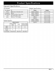
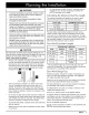
Verify
the
Package
Contents
Electrical
Service
Installation
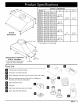
Unpack
the
parts
box
and
verify
that
all
parts
have
been
included
according
to
the
parts
list
on
page
5.
If
any
item
is
missing
or
damaged,
please
contact
the
dealer
immedi-
ately.
Do
not
install
a
damaged
or
incomplete
appliance.
Make
sure
you
have
everything
necessary
for
proper
instal-
lation
before
proceeding.
Mounting
Location
Preparation
WARNING
The
electric
service
to
the
range.hood
should
be
installed
only
by
a
licensed
electrician.
WARNING
».The-electrical
service
to
the
range
hood
should
be
installed
only by.a
licensed-electrician.
«Observe
all
governing
codes
and
ordinances
during
site
preparation
and
installation.
Contact-your
local
building
department
for
further
information.
*.Failure.to
properly
anchor
the
hood
to
the
wall
may
resultin
personal
injury.due
to
the
unit
falling
off
the
wall.
«To.
avoid
an
electric
‘shock
hazard
and
property
dam-
age,
locate
electric
wires.and
water
pipes
and-avoid
drilling
or-cutting
in
the
vicinity.
«Use
the
temporary
mounting
brackets.
only
to
hold
the
hood
in
place
until
permanent
anchoring
is
installed.
*
Temporary
mounting
brackets,
and
the
screws
and
anchors
to
hold
them
in
place
during
installation
are
provided
with
the
hood.
Two
anchors
and
screws
are
used
per
bracket.
*
Determine
the
number,
size
and
type
of
anchors
required
to
attach
the
hood
permanently
to
the
wall
and/or
the
cabinets
based
on
the
type
of
installa-
tion
and
the
weight
chart
on
page
3.
*
Make
sure
the
mount-
ing
surface
is
properly
K-47
reinforced
to
handle
the
I I
full
weight
of
the
hood.
If
mounting
the
unit
to
a
I
drywall
or
plastered
sur-
|
face,
install
a
reinforced
mounting
block
between
the
studs
behind
all
hood
mounting
locations.
You
may
attach
screws
directly
to
the
studs
and
cabinets
I
if
they
line
up
with
the
I
mounting
holes
in
the
back
I
and
top
of
the
hood.
If
Sy"
mounting
the
hood
to
brick
or
masonry,
select
anchors
capable
of
holding
the
full
weight
of
the
hood.
nn
roc
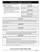
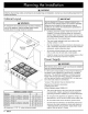
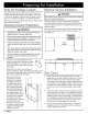
Install
a
junction
box
in
the
vicinity
of
the
hood
electri-
cal
access
holes
according
to
local
codes.
Install
it
either
behind
or
above
the
hood.
The
diagram
below
shows
sug-
gested
locations.
Drill
7/8”
holes
in
the
wall
or
cabinet
as
necessary
to
allow
the
wiring
to
pass
through
into
the
hood.
See
page
4
for
hole
locations.
Suggested
~
oe
1_electrical
|
|
location
;
po
EES
I
I
Hood
I
i
location
'
e
e
Duct
Cutout
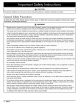
1.
Using
a
pencil,
draw
the
vertical
center
line
for
the
range
hood
on
the
wall.
Extend
the
line
down
10”
(25.4
cm)
from
where
the
top
of
the
hood
will
be
located.
The
center
line
for
the
hood
is
usually
halfway
between
the
cabinets
at
the
installation
location
or
the
same
as
the
center
line
of
the
cooktop
or
range.
The
line
will
be
used
to
line
up
the
mounting
brackets
during
installa-
tion.
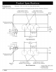
2.
Locate
the
center
lines
for
the
duct
cutout(s)
according
to
the
dimensions
on
page
4.
For
installations
venting
through
the top
of
the
hood,
use
the
top
dimensions
to
locate
the
center
lines
on
the
ceiling
or
cabinet bottom.
For
installations
venting
through
the
back
of
the
hood,
use
the
back
dimensions
to
locate
the
center
lines
on
the
back
wail.
See
the
diagrams
on
the
right.
3.
Cuta
hole
for
the
duct
to
pass
through
11”
(28
cm)
in
diameter.
Center
it
on
the
center
lines.
Dual
exhaust
models
require
two
(2)
holes.
8)
dacor