
Installation Instructions

3
Electrical Requirements
WARNING
To avoid an electric shock hazard, the power supply must meet the
specifications below. The owner shall ensure the electrical service
meets the requirements in this section and the outlet is installed by a
licensed electrician.
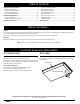
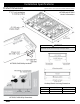
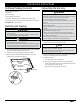
• A 42” power cord with a 3-prong, grounding plug is attached
to the chassis’ bottom in the right-rear corner. You must insert
the plug in a dedicated, grounded 3-prong electrical outlet
installed by a licensed electrician.
HCT305G/-365G (bottom)
• The electrical installation, including minimum-supply wire size
and grounding, must be done according to National Electric
Code ANSI/NFPA 70* and local codes and ordinances. You may
obtain a copy of this standard from:
National Fire Protection Association
1 Batterymarch Park
Quincy, MA 02269-9101
• The correct voltage, frequency, and amperage must be
supplied to the electrical outlet according to the product
data label on the chassis bottom. (See the Gas/Electrical
Requirements table on this page.)
• Position the electrical outlet so the power cord may be easily
disconnected if the unit needs service.
Gas-Supply Requirements
• Verify that the cooktop matches your provided gas service
(natural gas or liquid propane).
• If using the cooktop above 4000 ft. (1219 m) elevation, ensure
it is equipped for high-altitude operation. (Such units have
an “H” at the end of their model number on the product-data
label; see the Product Data Label section.)
• Units equipped for liquid-propane have “LP” in the model num-
ber on the product-data label.
• Check local building codes for the proper installation method.
If no local code exists, follow National Fuel Gas Code ANSI
Z223.1/NFPA 54.
• An external, manual shut-off valve must be installed between
the gas-supply line and the cooktop so gas to the cooktop can
be shut on/off.
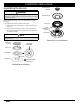
• Use only the provided regulator, which must be installed
between the cooktop gas inlet and the gas shut-off valve.
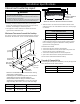
• Because the regulator inlet accommodates a 3/4” gas line, and
the cooktop inlet is a 1/2” male NPT fitting, a 3/4”-to-1/2” reduc-
er is included with the cooktop. (See HCT305G/-365G at left.)
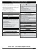
Gas/Electrical Requirements*
HCT305G_NG
HCT365G_NG
HCT305G_LP
HCT365G_LP
Gas Type Natural gas Liquid propane
Manifold Pressure 5” Water column 10” Water column
Min. Gas-Supply Pressure** 6” Water column 11” Water column
Max. Gas-Supply Pressure 1/2 psi
Total Connected Load 0.25 Amp. (30 Watts)
Circuit Requirement 120 Vac, 60 Hz, 15 Amp.
*This gas/electrical data is for reference only. If this data conflicts with the
product-data label, use the data on the label.
**The gas-supply pressure for testing the regulator setting shall be at least
1-in. water column (249 Pa) above the specified manifold pressure.
Important Safety Instructions