
Installation Instructions


4
Installation Planning
System Layout
WARNING
To avoid the risk of fire due to the unit overheating:
DO NOT• install this blower with a hood or raised vent
that has an internal blower.
DO NOT• install more than one blower to increase
the length of the duct run. Even small differences
between blower air flow rates can greatly reduce the
air drawn by the hood or raised vent.
Consult the installation instructions for the raised vent •
or hood for complete layout and duct system plan-
ning instructions. Observe all location and duct system
design instructions.
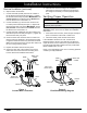
To minimize noise, install the blower at the mid-point •
between the raised vent or hood and the duct system
exhaust. Minimum recommended distance from the
vent/hood or exhaust is 5 feet.
General System Design Notes
Wire the remote blower to turn on when the raised •
vent or hood is turned on by running a piece of conduit
parallel to the duct work and connecting it to the raised
vent or hood on one end and the in-line blower on the
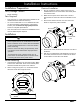
other. There are two 1/2” electrical access hole knock
outs in the sides of the blower’s electrical access panel.
Electrical Access Knock-outs
Select a location that can properly support or can be •
reinforced to support the weight of the blower.
Model Number Weight
ILHSF8 22 lbs. (10 kg.)
ILHSF10 31 lbs. (14 kg.)
Install the blower so that it can be removed if service is •
required.
Plan the installation so that all minimum dimensions •
are met or exceeded. All contact surfaces between the
blower and any mounting surfaces must be solid and at
right angles.
The mounting surface must be thick enough to accom-•
modate screws 2” in length.
Electrical Specifications
Electrical Supply Requirements
The power for this blower is supplied via 1/2” 3-wire •
conduit (not included) by an approved Dacor hood or
raised vent. The conduit is installed between the hood
or raised vent and the blower and shall be terminated
on each end by a 1/2” UL certified strain relief. The
power is turned on and off by the power switch on the
approved ventilation device.
The correct voltage, frequency and amperage must be •
supplied to the hood or raised vent and the blower from
a grounded, single phase circuit that is protected by a
properly sized circuit breaker or time-delay fuse. The
circuit must have the capacity to supply the combined
power requirements for the hood or raised vent and the
in-line blower. See the installation instructions for the
hood or raised vent to determine total power require-
ments in combination with the blower electrical specifi-
cations.
Blower Electrical Specifications
Model
Number*
Power
Requirements**
Nominal
Blower Rating***
ILHSF8
120 Vac, 60 Hz,
3.5 Amp.
600 CFM
ILHSF10
120 Vac, 60 Hz,
4.5 Amp.
1100 CFM
* All models are thermally protected.
** In addition to the hood or raised vent
***
At 0 inches static pressure. See Technical Data for
actual rating and other performance data.
The above specifications are for reference only, See the
data label on the blower for exact specifications. If the
above specifications vary from the label on the blower, use
the data on the blower label.
It is the owner’s responsibility to ensure that the electri-•
cal connection of this blower is performed by a qualified
electrician. The electrical installation, including mini-
mum supply wire size and grounding, must be in accor-
dance with the National Electric code ANSI/NFPA* (or
latest revision) and local codes and ordinances.
* A copy of the specification may be obtained from:
National Fire Protection Association
1 Batterymarch Park
Quincy, Massachusetts 02269-9101
If the electrical service provided does not meet all prod-•
uct specifications, or does not conform to the NEC or
local standards, do not proceed with the installation.
Call a licensed electrician to correct the electrical ser-
vice before proceeding.
Product Specifications
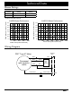
GRN
L1
BLU
BLK
GND
N1