
Downdraft Planning Guide


All specications subject to change without notice.
Phone: (800) 793-0093www.dacor.com
PLANNING
GUIDE
ERV3015, ERV3615, ERV36-ER, ERV48, ERV48-ER,
PRV30, PRV36, PRV48
Renaissance
Slim Chassis
Downdraft Vents
Document # PG08-001
Revised 02/28/14 Page 5/7
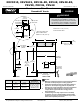
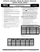
EXHAUST OUTLET LOCATION OPTIONS
FRONT VIEW
SIDE VIEW
All tolerances: ±1/16” (±1.6 mm) unless otherwise stated
Rear Exhaust Knock Out (3 ¼
”
X 10”)
3”
Vertical center line of rear exhaust knock out lines up with vertical
center line of chassis
The vertical center line of bottom knock out is offset 3”
Side Exhaust Knock Outs (1 ⅝
”
X 16”)
Bottom Exhaust Knock Out (1 ⅝
”
X 16”)
Motor
cover
Front of unit
26" (66.0 cm)
6 1/2
”
(16.5 cm)
1 1/8
”
(2.9 cm)
C
L
C
L
C
L
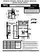
2” X 16” TO 3 1/4” X 10” TRANSITION
(INCLUDED)
3 ¼ x 10 to duct work
2 x 16, connects to
side or bottom exhaust
on downdraft
1"
(2.5 cm)
5"
(12.7 cm)
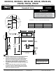
■ There are 7/8” access holes in the bottom and side of the downdraft
vent for connecting the blower wiring and strain relief. The blower
must be wired to turn on when the downdraft vent is turned on. When
installing a remote or in-line blower, run the blower wiring/conduit
parallel to the duct work, connecting it to the downdraft vent on one
end and the blower on the other.
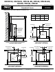
■ Access from the front of the cabinet to the chassis and the electrical/
gas supplies of both appliances must be provided for inspection and
service. Any drawers or shelves must be easy to remove for access to
the cooktop, downdraft vent and utilities.
Front of unit
Cabinet blower -
option on ERV3015,
and ERV3615 only
Connection to
cabinet blower
Blower wiring
access hole
Blower wiring
access hole
Connection to
remote/in-line
blower
ELECTRICAL LAYOUT