AIO(DAE) 0.3.30 3:39 PM ∆‰¿Ã¡ˆ1 User’s Manual DAEWOO TELECOM LTD.
AIO(DAE) 0.3.30 3:39 PM ∆‰¿Ã¡ˆ2 CONTENTS Starting 3 1. How to use this manual 3 2. Check Items 4 3. System Setting 5 Ch1.System Configuration 6 1. Front configuration 6 2. Rear configuration 7 Ch2. Start to Install 8 1. Plugging the mouse/keyboard 8 2. Plugging the Power Cord 9 3. Plugging the RJ11 Phone line 10 Ch3. System Disassembling & assembling 11 1. Disassemble Drawing 12 2. Upgrading Memory and Replacing Backup Battery 17 3. Assemble Drawing 20 Ch4.Monitor 23 1.
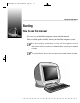
AIO(DAE) 0.3.30 3:39 PM ∆‰¿Ã¡ˆ3 Daewoo Telecom Lt Starting How to use this manual It is very easy to install the computer system with this manual. Please read this guide carefully, before you install the computer system. For your safety, remember to turn off the system and to disconnect all the cords and cables before opening the system chassis. To avoid electric shock, do not open the monitor frame chassis. [figure.
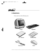
AIO(DAE) 0.3.30 3:39 PM ∆‰¿Ã¡ˆ4 2.Check Items Check your boxes for the following items.
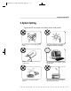
AIO(DAE) 0.3.30 3:39 PM ∆‰¿Ã¡ˆ5 Daewoo Telecom Lt 3.System Setting Operate the PC on a sturdy level surface such as desk or table. Please do not overload the power socket. Place the system away from high temperature and direct sunlight. Do not place magnetic objects close to the system. Keep distance between the system and the wall. Avoid dust or moisture from the system. Place the system away from radio or any electronic receivers.
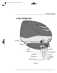
AIO(DAE) 0.3.30 3:39 PM ∆‰¿Ã¡ˆ6 Ch.1 System Configuration 1.Front configuration Micro-phone Monitor HDD LED Power Butto FDD eject button CD-ROM Drive LED Floppy Disk Drive CD-ROM Drive eject button FDD LED CD-ROM Drive [figure.
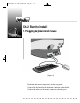
AIO(DAE) 0.3.30 3:39 PM ∆‰¿Ã¡ˆ7 Daewoo Telecom Lt 2.Rear Configuration AC Power Speaker Phone Mouse Keyboard Tel Line(to the Serial port Parallel port MIDI/Game port [figure.
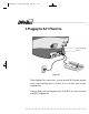
AIO(DAE) 0.3.30 3:39 PM ∆‰¿Ã¡ˆ8 Ch.2 Start to Install 1.Plugging keyboard and mouse [figure. 4] Keyboard and mouse connector is on the rear panel. Connect the keyboard to the keyboard connector colored blue. Connect the mouse to the mouse connector colored green.
AIO(DAE) 0.3.30 3:39 PM ∆‰¿Ã¡ˆ9 Daewoo Telecom Lt 2.Plugging the power cord [figure. 5] D@eBox Computer System applies both 110/220V power range withou any setting action. Just plug the power cord into your PC and connect the cord to th grounded outlet. Do not connect power cable to the power outlet until you finish all the preceding steps.
AIO(DAE) 0.3.30 3:39 PM ∆‰¿Ã¡ˆ10 3.Plugging the RJ11 Phone line Tel Line(to the wa Phone [figure. 6] With telephone line connectivity, you can network PCs located anywher in the same building where you have access to jacks from a singl telephone line. Connect phone jack and telephone line of the PCs you want to networ with RJ11 telephone line.
AIO(DAE) 0.3.30 3:39 PM ∆‰¿Ã¡ˆ11 Daewoo Telecom L CH3. System disassemble & assemble This model provides many convenient options that gives you more syste flexibility. This chapter describes how to install optional part inside th computer and remove and replace the computer cover and expansion-ca cage. Are you ready? For easier work with inside your computer , please check out you hav proper lighting and a clean work space.
AIO(DAE) 0.3.30 3:39 PM ∆‰¿Ã¡ˆ12 1. Disassembling Drawing This section describes how to disassemble PC for adding RAMs, changin battery, installing modem card etc. It is very important to check if the AC power cable is removed from PC before you disassemble your PC. If the AC power cable is removed form your PC, you may start disassembling. Opening the Computer 1) Place a soft stuff (example : towel, cloth etc.) on the front of computer. Place a soft stuff on the front of computer [figure.
AIO(DAE) 0.3.30 3:39 PM ∆‰¿Ã¡ˆ13 Daewoo Telecom Lt 2) As you could see [figure.8], there are 5 screws and loose 4 of them which is indicated as ① to separate the thin plate. ① Loose these sc [figure.
AIO(DAE) 0.3.30 3:39 PM ∆‰¿Ã¡ˆ14 3) After you separate the thin plate as you can see in [figure. 9], loose screws indicated as ➁ to separate transparent case ➂, first remove th speaker cable (➃) which is connected to speaker at this moment. ➁ loose these ➂ transparent cose ➃ remove the speaker cable [figure.
AIO(DAE) 0.3.30 3:39 PM ∆‰¿Ã¡ˆ15 Daewoo Telecom Lt 4) After you separate transparent case, loose 3 screws indicated as ⑤ to separate the body of PC. [figure. 10,11] shows how you can separat body and monitor. Please be cautious when you pull out the bod because the body and monitor is connected with cable. If you pull ou the body little bit first then remove the cable, there will be no problem [figure. 12] shows after the monitor and body is separated. ⑤ Loose these screws [figure. 10] [figure.
AIO(DAE) 0.3.30 3:39 PM ∆‰¿Ã¡ˆ16 5) Description for each part of main board and interface board locate beneath the monitor.[figure. 13] VGA(9pin) VGA(6pin) Power(24pin) (M/B, HDD, LED(7pin) Mic(2pin) [figure.
AIO(DAE) 0.3.30 3:39 PM ∆‰¿Ã¡ˆ17 Daewoo Telecom Lt 2. Upgrading Memory and Changing the backup Battery This section is to describe that upgrading memory and Changing th backup battery. Upgrading Memory This model has 64 Mbytes memory as a default and you can upgrade ma 256 Mbytes when you need. How to install 1) Locate the two clips that hold the memory module in place. One cli holds the left edge of the module and the other clip holds the right edge 2) Push both clips away from the socket.
AIO(DAE) 0.3.30 3:39 PM ∆‰¿Ã¡ˆ18 How to remove 1) Locate the two clips that hold the memory module in place. One cli holds the left edge of the module and the other clip holds the right edge 2) Push one clip away from the module. Then, while holding the modul with one hand, push the other clip away from the module. DIMM Memory module DIMM Socket 3) Lift the module out of the socket.
AIO(DAE) 0.3.30 3:39 PM ∆‰¿Ã¡ˆ19 Daewoo Telecom Lt Changing the Battery 1) A mercury cell is located in the center of main board to keep setup dat of CMOS 2) If you see the case part, you could find protruding part(➁). Kee pushing this protruding part and remove existing cell then install new cell. If you are using metallic driver to push, try not to touch any othe part with the metallic tool. There is the danger of an explosion if the battery is incorrectl replaced.
AIO(DAE) 0.3.30 3:39 PM ∆‰¿Ã¡ˆ20 3. Assembling Drawing 1) You can assemble PC with reverse order of disassembling. First of al please check if all part is attached firmly. 2) Connect body and monitor with cable. 3) Put in PC body after fitting ① and ➁.(FDD,CDROM is front)[figure. 15 4) Drive these screw. [figure. 16] ① ➁ ➂ [figure. 15] [figure.
AIO(DAE) 0.3.30 3:39 PM ∆‰¿Ã¡ˆ21 Daewoo Telecom Lt 5) After finish assembling body part, combine transparent case like [figure 17], drive these crews (➃), and also connect to the speak cable(⑤). ⑤ ➃ Drive these screws [figure. 17] 6) Fit the thin plate shown [figure. 18] and drive these screw (➅). ➅ Drive these screw [figure.
AIO(DAE) 0.3.30 3:39 PM ∆‰¿Ã¡ˆ22 7) Stand your PC, connect the power cable and turn on. [figure.
AIO(DAE) 0.3.30 3:39 PM ∆‰¿Ã¡ˆ23 Daewoo Telecom L Ch.4 Monitor 1.Factory preset display mode Preset mode VGA VEGA Resolution H(Pixel) V(Line) 640 350 720 400 640 480 640 480 640 480 800 600 800 600 800 600 1024 768 1024 768 1280 1024 Frequency H(KHz) V(Hz) 31.5 70 31.5 70 31.5 60 37.5 75 43.2 85 37.9 60 46.9 75 53.6 85 48.3 60 68.7 85 64.0 60 2.
AIO(DAE) 0.3.30 3:39 PM ∆‰¿Ã¡ˆ24 3.OSD CONTROL PROGRAM General [figure. 20] - Brightness : Adjust the brightness of the entire image. - Contrast : Adjust the contrast of image, the difference between light an dark areas on the screen. - Horizontal Size : Adjust the display width (Horizontal size). - Horizontal Position :Adjust the position of the display horizontally(Lef or Right). - Vertical Size :Adjust the display height (Vertical size).
AIO(DAE) 0.3.30 3:39 PM ∆‰¿Ã¡ˆ25 Daewoo Telecom Lt Geometry [figure. 21] - Pincushion : Adjust the left and right margins for more convex or mor concavemargins. - Pin Balance : Adjust the side balance when the sides of the screen ar bowed towards left or right. - Parallelogram : Adjust the parallelogram when the screen is leaning lef or right. - Trapezoid : Adjust the trapezoid of the screen by moving the lines inwar or outward. - Rotation : Adjust the rotation when the screen is tilted left or right.
AIO(DAE) 0.3.30 3:39 PM ∆‰¿Ã¡ˆ26 Color [figure. 22] - Red Gain : Adjust the red gain. - Green Gain : Adjust the green gain. - Blue Gain : Adjust the blue gain. - Red Cutoff : Adjust the red cutoff. - Green Cutoff : Adjust the green cutoff. - Blue Cutoff : Adjust the blue cutoff.
AIO(DAE) 0.3.30 3:40 PM ∆‰¿Ã¡ˆ27 Daewoo Telecom Lt Utility [figure. 23] - Degauss : Degauss the display and restore image quality. - GD-Recall : Return the original value - GD-Save : Save the setting value - Horizontal Moire : Adjust the horizontal picture moire cancellation. - Vertical Moire : Adjust the vertical picture moire cancellation. - H-Focus : Adjust the focus image.
AIO(DAE) 0.3.30 3:40 PM ∆‰¿Ã¡ˆ28 Ch.5 Mother board 1.
AIO(DAE) 0.3.30 3:40 PM ∆‰¿Ã¡ˆ29 Daewoo Telecom Lt Item Audio Specifications - Built in Trident 4DWAVE-DX-1 PCI Audio controller - Crystal 4297A stereo audio CODEC or compatible part - Built in 1.5W Audio Amplifier - Integrated with internal speaker - Audio in/audio out BIOS - Phoenix PnP BIOS - 2MB Flash ROM LAN/HPNA Controller - Built in Intel 21145 10Base-T/HomeRun controller (Option) - Support Ethernet 10Base-T and HPNA 1.
AIO(DAE) 0.3.30 3:40 PM ∆‰¿Ã¡ˆ30 2.Layout [figure.
AIO(DAE) 0.3.30 3:40 PM ∆‰¿Ã¡ˆ31 Daewoo Telecom Lt 3.
AIO(DAE) 0.3.30 3:40 PM ∆‰¿Ã¡ˆ32 Ch.6 Bios Setup The SETUP program is a built-in program that allows configuration o functions and devices of the system. This chapter provides information on how the setup program allows you t configure the function and device of your computer and how to configur each item on the setup menus. ■ Changing/Saving SETUP 1. SETUP can be invoked when the power is turned on or software reset initiated.
AIO(DAE) 0.3.30 3:40 PM ∆‰¿Ã¡ˆ33 Daewoo Telecom Lt 4. <+>,<-> and the space bar will scroll the current field’s value. 5. To change a value of configuration, repeat the procedure 2 through 4. 6. If you press, the Exit menu will be displayed. Save your changes to CMOS and exit system Setup. ■ Reconfiguring SETUP with Default Values 1. During boot-up secquence, press to display the SETUP menu. 2. Press to go to the ‘Exit’ menu. 3.
AIO(DAE) 0.3.30 3:40 PM ∆‰¿Ã¡ˆ34 Main Phoenix BIOS Setup Utility Security Power Boot Advanced System Time : System Date : [12:00:13] [07/04/1999] Legacy Diskette A : Legacy Diskette B : [1.44/1.25 MB 3 1/2”] [Disabled] Primary Master Primary Slave Secondary Master Secondary Slave [Qudntum XXX] [None] [CD-ROM] [None] Exit Item Specific Help , , or selects field.
AIO(DAE) 0.3.30 3:40 PM ∆‰¿Ã¡ˆ35 Daewoo Telecom Lt -System Date This option displays the current system date. Use <+> and <-> keys to change the values. Press to move from the Month to the Date to the Year field. -Legacy Diskette A : / Legacy Diskette B : These options define wether to use the ’A’ drive/’B’ drive and set the typ of floopy disk drive installed in each drive.
AIO(DAE) 0.3.30 3:40 PM ∆‰¿Ã¡ˆ36 2. Advanced Setup Menu Use this menu to set the Advanced Features available on your system’ chipset. Selecting “Advanced” from the Menu Bar displays the Advanced Menu which looks like this : Main Advanced PhoenixBIOS Setup Utility Security Power Boot Setup Warning Setting items on this menu to incorrect values may cause your system to malfunction.
AIO(DAE) 0.3.30 3:40 PM ∆‰¿Ã¡ˆ37 Daewoo Telecom Lt -Installed O/S Select the operating system installed on your system which you will us most commonly. (Note : An incorrecting setting can cause some operating systems t display unexpected behavior.) -Reset Configuration Data To reset PnP data, set the value to ‘Yes’. ‘Yes’ erase all configuration dat in ESCD, which stores the configuration settings for non-PnP plug-i devices. Select ‘Yes’ when required to restore the manufacture’s defaults.
AIO(DAE) 0.3.30 3:40 PM ∆‰¿Ã¡ˆ38 -Spread Spectrum When this item is Enabled, the EMI noise can be extremely minimized. -I/O Device Configuration. This item allows you to configure I/O device as following. • Serial port A/ Serial port B : Assign a port address to each serial port. • Parallel Port : Assign a port address to the parallel port. • Floopy disk Controller : Enable/Disable the Floopy disk controller. 3.
AIO(DAE) 0.3.30 3:40 PM ∆‰¿Ã¡ˆ39 Daewoo Telecom Lt Main PhoenixBIOS Setup Utility Security Power Boot Advanced Exit Item Specific Help Supervisor Password Is : User Password Is : Clear Clear Set Supervisor Password Set User Password [Enter] [Enter] Password on boot : Diskette access : Fixed disk boot sector : [Disabled] [Supervisor] [Normal] Supervisor Password controls access to the setup utility.
AIO(DAE) 0.3.30 3:40 PM ∆‰¿Ã¡ˆ40 -Set User Password Can set a User Password only when a supervisor password is set up. To clear the current password, just hit on New Password an confirm Password.(Maximum five characters can be used for a password.) -Password on boot If ‘Enabled’, entry of the password is required to boot up system. -Diskette access This item allow you to control access to diskette drives. If supervisor password is ‘Enabled’, access to the FDD is limited to th supervisor.
AIO(DAE) 0.3.30 3:40 PM ∆‰¿Ã¡ˆ41 Daewoo Telecom Lt 4.Power Setup Menu Use this menu to configure Power-Management features.
AIO(DAE) 0.3.30 3:40 PM ∆‰¿Ã¡ˆ42 -Power Buton Override Specify power button option as following: Enabled : Use Power Button as the Suspend/Resume Button and support sec Power override. Disaled : Use Power Button as Softoff Button. - Power Savings Specify Power Savings option as following : Disabled : Turn off Power Management. Customized : Can define the “Standby Timeout” and “Auto Suspen Timeout”. - Idle Mode Slows the CPU clock down when the system is inactive for a pre-define period of time.
AIO(DAE) 0.3.30 3:40 PM ∆‰¿Ã¡ˆ43 Daewoo Telecom Lt : Resuming from the Suspend Mode - By Pressing the Power switch, Keyboard, Mouse - When the modem rings(when “Resume On Modem” is set to “On”) - Accoring to the time set in the timer(When “Resume On Time” is set to “On”) Save To Disk(When the Suspend Mode is set to “Save To Disk”) Save system date into the hard disk and turn the system power off fo maximum power saving. :Entering into the Save To Disk Mode - On the ‘Shutdown’ command by Windows.
AIO(DAE) 0.3.30 3:40 PM ∆‰¿Ã¡ˆ44 5. Boot Setup Menu Use this menu to specify any drive as a boot drive. Selecting “Boot” from the Menu Bar displays the Boot menu, which look like this : Main PhoenixBIOS Setup Utility Security Power Boot Advanced Exit Item specific Help 1. 2. 3. 4. [Removable Devices] [Hard Drive] [ATAPI CD-ROM Drive] [Network Boot] Use < > or < > to select a device, then press <+> to move it up the list, or <-> to move it down the list. Press to exit this menu.
AIO(DAE) 0.3.30 3:40 PM ∆‰¿Ã¡ˆ45 Daewoo Telecom Lt -1/2/3/4 You can arrange the Boot Order List at the top of this menu to specify th order of the devices from which the BIOS will attempt to boot th Operating System. To move a device, first select it with up-or-down arrow keys, and move it up or down using the <+> and <-> keys. Note : If you have more than one hard drive, or more than one removabl devices, use the sub menus to specify which one to use on the boot orde list, as described in the following.
AIO(DAE) 0.3.30 3:40 PM ∆‰¿Ã¡ˆ46 6. Exit Setup Menu Exits the current menu. Selecting “Exit” from the Menu Bar displays the Exit menu, which look like this : Main Advanced PhoenixBIOS Setup Utility Security Power Boot Exit Saving Changes Exit Discarding Changes Load Setup Defaults Discard Changes Save Changes Exit Item specific Help Exit System Setup and save your changes to CMOS.
AIO(DAE) 0.3.30 3:40 PM ∆‰¿Ã¡ˆ47 Daewoo Telecom Lt -Exit Saving Changes Save current values and exit the SETUP program. -Exit Discarding Changes lgnore the changes and exit SETUP program. -Load Setup Defaults Assign default values to configuration fields. -Discard Changes lgnore the changes. -Save Changes Save current values to CMOS.
AIO(DAE) 0.3.30 3:40 PM ∆‰¿Ã¡ˆ48 * Other System Related Issues “Phdisk32” Utility(Phdisk32.exe) This utility creates a hidden file(save2disk.bin) on the HDD to store dat saved for the ‘Save To Disk’ mode. The intial file size is apporximatel 170MB (the maximum system memory is 160MB) and the size can b changed by the user. This utility file is located in the ‘System’ folder of th ‘EASY COMPUTER GUIDE’ CD. Run ‘Phdisk32.exe’ to view instruction.