S/M No. : Service Manual Auto Washer Model: DWF-200SL/200SM/200SW ✔ Caution : In this Manual, some parts can be changed for improving, their performance without notice in the parts list. So, if you need the latest parts information, please refer to PPL(Parts Price List) in Service Information Center (http://svc.dwe.co.kr). Oct.
AUTO WASHER AUTO WASHER AUTO WASHER AUTO WASHER AUTO WASHER AUTO WASHER AUTO WASHER AUTO WASHER AUTO WASHER AUTO WASHER AUTO WASHER AUTO WASHER AUTO WASHER AUTO WASHER AUTO WASHER AUTO WASHER AUTO WASHER AUTO WASHER AUTO WASHER AUTO WASHER AUTO WASHER AUTO WASHER AUTO WASHER AUTO WASHER AUTO WASHER AUTO WASHER AUTO WASHER AUTO WASHER AUTO WASHER AUTO WASHER AUTO WASHER AUTO WASHER AUTO WASHER AUTO WASHER AUTO WASHER AUTO WASHER AUTO WASHER AUTO WASHER AUTO WASHER AUTO WASHER AUTO WASHER AUTO WASHER AUTO WAS
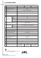
1. SPECIFICATIONS No. ITEM DWF-200SL 1 POWER SOURCE 2 POWER CONSUMPTION 3 WEIGHT 4 DIMENSION (WxHxD) 5 WASHING COURSE DWF-200SM DWF-200SW A.C 110V/60Hz , A.C 220V/50Hz , A.C 220V/60Hz 550W 47kg(Non-Pump) / 48kg(Pump) 630 x 1,015 x 700 mm FULL AUTOMATIC 6 COURSES (FUZZY, BLANKET, ECONOMY, BABY CARE, SPORTS WEAR, DELICATE) 6 7 8 WATER CONSUMPTION 245ℓ HIGH 90ℓ WATER LEVEL MED 70ℓ SELECTOR LOW 59ℓ SMALL 49ℓ 0.03MPa ~ 0.8MPa OPERATING WATER PRESSURE (0.3kgf/cm2 ~ 8kgf/cm2 = 2.
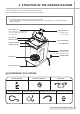
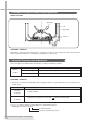
2. STRUCTURE OF THE WASHING MACHINE The parts and features of your washer are illustrated on this page. Become familiar with all parts and features before using your washer. NOTE • The drawings in this book may vary from your washer model. They are designed to show the different features of all models covered by this book, Your model may not include all features. • HOT WATER TAP • COLD WATER TAP After using the washer, close the water tap.
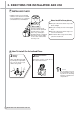
3. DIRECTIONS FOR INSTALLATION AND USE ■ INSTALLING PLACE Install the washer on a horizontal solid floor. If the washer is installed on an unsuitable floor, it could make considerable noise and vibration. 10Cm 25cm Never install in these places Keep the machine body more than 25cm apart from the wall surface. It will make easy cleaning the drain filter which is equipped at the back side of it. And if it comes into contract vibration may occur. ● The place where it would be exposed to direct sunlight.
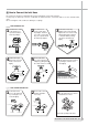
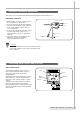
■ How to Connect the Inlet Hose Be careful not to mistake in supplying between the hot(maximum : 50˚C) and cold water. In using only one water tap or in case of attached one water inlet valve, connect the inlet hose to the cold water inlet valve. Do not over tighten : This could cause damage to couplings. FOR ORDINARY TAP 1 Pull down the collar of the inlet hose to separate it from the water tap adapter.
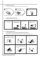
CLEANING THE LINT FILTER • This washer has two Lint Filters in the top TUB in order to filter off lint and fuzz. 1 2 Pull the Filter frame upward. 3 Return the filter as it was, and insert the filter frame into the slot. 3 Pull the inlet filter out. 4 Remove the dirt from the inlet filter with a brush. Turn the lint filter inside out, wash to the lint off with water. Lint Filter Filter Frame CLEANING THE WATER INLET FILTER • Clean the filter when water leaks from the water inlet.
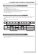
4. FEATURE AND TECHNICAL EXPLANATION Feature of the Washing Machine 1 First applying the Radical Technology in the world ... go beyond washing, sterilize your clothes and deodorize a bad smell(Option). 2 The first air bubble washing system in the world. 3 Quiet washing through the innovational low-noise design. 4 Improving washing performance by more than 35%, while reducing power consumption by 40%. 5 The laundry detergent dissolves well in water because of the air bubble washing system.
Functional Principle of Bubble Washing Machine ACROSS SECTION Air bubble Tub Outer tub Pulsator FUNCTIONAL PRINCIPLE Bubble Motor supplies the air from the bottom of outer tub to the inner space of pulsator, the air is dispersed by the rotation of pulsator. Air-bubble is created by the centrifugal force, and rises up. Automatic Drainning time Adjustment This system adjusts the draining time automatically according to the draining condition. Good draining The washer begins spin process after drainage.
Automatic Unbalance Adjustment This system is to prevent abnormal vibration during intermittent spin and spin process. FUNCTIONAL PRINCIPLE Contact of safety switch 1. When the lid is closed, the contact lever A of the safety switch is “ON” position. 2. In case that wash loads get uneven during spin, the outer tub hits the safety switch due to the serious vibration, and the spin process is interrupted. 3. In case that P.C.B.
Lint Filter Much lint may be obtained according to the kind of clothes to be washed and some of the lint may also stick to the clothes. To minimize this possibility a lint filter is provided on the upper part of the tub to filter the wash water as it is discharged from the water channel. It is good to use the lint filter during washing. Filter HOW TO REPLACE LINT FILTER 1. Pull the filter frame upward. 2. Turn the lint filter inside out, and wash the lint off with water. 3.
Gear Mechanism Ass’y The proper water currents is made by the rotation of pulsator at a low speed to prevent the damage to the small sized clothes. Sun gear Internal gear Planetary gear Motor 1800 r.p.m (60Hz) 1500 r.p.m (50Hz) Pulsator Gear unit as 1 revolution Motor V-Belt Gear Unit as 130-150r.p.m(60Hz) 125-140r.p.m(50Hz) Spinner Pulley 5 revolutions Pulsator 710-740r.p.m(60Hz) 640-675r.p.m(50Hz) Tub Gear pulley Directly 710-740r.p.m(60Hz) 640-675r.p.
5. DIRECTIONS FOR DISASSEMBLY AND ADJUSTMENT Warning BEFORE ATTEMPTING TO SERVICE OR ADJUST ANY PART OF THE WASHING MACHINE, DISCONNECT THE POWER CORD FROM THE ELECTRIC OUTLET. Gear Mechanism Ass’y Replacement GEAR MECHANISM ASS’Y REPLACEMENT 1 Remove 1 screw from the PANEL F. 2 Separate PANEL F by pushing PANEL F washing to the right. 3 Remove 4 screws and separate PLATE T from machine. Remove screw Pushing Remove 4 screws 4 Remove 4 screws and separates COVER TUB from TUB ass’y.
6 Unscrew PULSATOR mounting screw and separates PULSATOR form TUB ass’y. 7 Unscrew special nut using ‘T’ type box wrench. 8 Separate TUB I from TUB ass’y. 9 Lay the top of the washing machine on the floor. 0 Unscrew 4 special bolts of GEAR PROTECT using a box wrench and separate GEAR PROTECT . q Unscrew 4 special bolts of GEAR MECHANISM using a box wrench. w Separate GEAR MECHANISM and BELT V. NOTES To assemble the gear mechanism ass’y, reverse the disassembly procedure.
MOTOR DRAIN AND VALVE REPLACEMENT (NON PUMP MODEL) 1 Lay the top of the washing machine on the floor. 2 Unscrew 2 special bolts mounting MOTOR DRAIN. 3 Take out the wire of MOTOR DRAIN. 4 Separate MOTOR DRAIN from BASE. 5 Turn the valve using screw driver as shown picture. 6 Separate the valve lid from VALVE DRAIN ass'y.
6.
How to check the clutch spring CHECKING METHOD IN THIS CASE, YOU MUST EMPTY THE SPIN TUB FIRST. 1) TO CHECK THE REVOLUTION OF SPIN TUB. IF THE SPIN TUB DOES NOT REVOLVE AND ONLY THE PULSATOR IS TURNING, THAT IS CLUTCH SPRING DEFECT. 2) TO CHECK THE SPIN SPEED(RPM) BETWEEN SPIN TUB AND PULSATOR. IF YOU FIND THE DIFFERENT SPIN SPEED BETWEEN SPIN TUB AND PULSATOR, THIS IS ALSO CLUTCH SPRING DEFECT. IN THIS CASE, WE ARE GOING TO SUPPLY THE CLUTCH BOSS ASSEMBLY INSTEAD OF GEAR MECHANISM ASSEMBLY.
The Process Of Disassembling Disassembling 1 No. Process Notice Use wrench or driver. - ratchet handle - extension bar - socket : 10mm 1 Remove the protector Release screws marked 4-point 2 Remove the v-belt Use fixing jig for pulley as to see fig 1. and 17mm-socket for nut. 3 Loosen the fastening nut Take out plain washer if it has.
Disassembling 2 No. 5 Process Notice Disassemble the pulley Catch the boss and pull upward with spiral rotate in the clockwise direction. 6 Disassemble the clutch boss assembly 7 Separate coupling from clutch boss ass’y Clean the drum plate, coupling surface and contact face between drum plate and coupling. 8 18 THE REPAIR METHOD Cleaning It is necessary to keep cotton piece goods being dry and clean.
The Process Of Assembling Assembling 1 No. Process Notice Check the uneven face of coupling is assembled upward. 1 Assemble the coupling 2 Assemble the new clutch boss ass’y 3 Assemble the pulley - Push in the clutch boss ass’y with rotating on the clockwise direction. - After assembling, rotate on the clockwise more 2~3 teeth and pull out the pulley shaft upward. If there was plain washer, you have to assemble plain washer the first and then assemble spring washer.
Assembling 2 No. Process Assemble the fastening nut 5 6 Notice - Use fixing jig and 17mm socket wrench as if disassembling, as fastening torque about 100~200kgf-cm. - Check the end-play, up and downward and check the binding force, too much or not on bi-direct of rotation. Assemble the belt 7 Assemble the protector Synchronous Motor 8 Finally, check the interference depth both clutch tip and clutch boss(3.5~4.5mm). Drain Valve Final checking Clutch Tip 3.5~4.
7. TROUBLE SHOOTING GUIDE NOTES 1. When replace the P.C.B. ASS’Y do not scratch the surface of the P.C.B. ASS’Y. 2. Disconnect the power cord from the electric outlet. Concerning Water Supply PROBLEM CHECK POINT CAUSE Do you open the water tap? NO SOLUTION Open the water tap. YES YES Is the filter of the water inlet valve clogged with dirt? Clean the filter. NO WATER IS NOT SUPPLIED. Increase the water pressure. NO Is the water pressure sufficient? (0.
PROBLEM CHECK POINT Does the water supply continue while the power is turned off? CAUSE SOLUTION YES The water inlet valve is defective. Change the water inlet valve. YES The triac of P.C.B is defective. Change the P.C.B ASS’Y. NO Does the water supply start as soon as you press the power switch? NO WATER SUPPLY IS NOT STOPPED.
Concerning Draining PROBLEM CHECK POINT Do you install the drain hose properly? CAUSE NO SOLUTION Improper installation. Install the drain hose properly. Malfunction of drainage by the foreign substance. Remove the foreign substance from the drain housing. The drain motor is defective. Change the drain motor. P.C.B ASS’Y is defective. Change the P.C.B ASS’Y. YES THE WASHER DOES NOT DRAIN.
Concerning Spinning PROBLEM CHECK POINT CAUSE SOLUTION YES Close the lid. Is the lid open? NO Does the door switch operate normally? NO Door switch is defective. Change the door switch. Safety switch is defective. Change the safety switch. Improper connection of the connector. Connect the connector properly. P.C.B. ASS’Y is defective. Change P.C.B ASS’Y. Drain motor is defective. Change the drain motor. P.C.B ASS’Y is defective. Change the P.C.B ASS’Y. V-belt is defective.
Concerning Operating PROBLEM CHECK POINT CAUSE SOLUTION NO Is the plug connected to electric outlet? Connect the plug. YES YES Is Fuse opened? Change fuse. NO THE INDICATOR LAMPS(L.E.D) DO NOT LIGHT UP WHEN THE POWER BUTTON IS PRESSED. Is the condition of power button good? NO Is the connector of the P.C.B. ASS’Y connected properly? NO ABNORMAL NOISE DURING WASH PROCESS. Improper connection of the connector. Connect the connector properly. Transformer is defective. Change Transformer. P.
8. PRESENTATION OF THE P.C.B ASS’Y Concerning Error Message MESSAGE CAUSE SOLUTION Improper installation of drain hose. Install drain hose properly. The drain hose is blocked up by foreign matter. Remove foreign matter from drain hose. Drain motor is inferior. Change drain motor. The water tap is closed. Open the water tap. The water inlet filter clogged. Clean the water inlet filter. It passes over the 60 minutes, yet it doesn’t come to assigned water level.
9.
■ Parts Diagram TOP DWF-200SL A19 LEFT A17 A18 A16 FRONT A01 A20 A04 A21 A02 A22 A07 A05 A03 A23 A09 A24 A06 A08 A25 DWF-200SM/200SW A10 A11 A26 A17 A18 A12 A13 A27 A14 A22 A28 A15 28 PARTS DIAGRAM
TOP LEFT B02 FRONT B01 B07 B08 B03 B05 B04 B06 B13 B14 B09 PUMP OPTION B10 B15 B11 B16 B12 PARTS DIAGRAM 29
TOP C16 LEFT FRONT C02 C01 C06 C07 C03 C08 C04 C15 C13 C14 C09 C12 C10 C11 30 PARTS DIAGRAM
TOP LEFT FRONT PARTS DIAGRAM 31
■ Parts List No. A01 PARTS NAME PANEL *B PARTS CODE DESCRIPTION 36142T4600 DWF-200S, ABS 36142T4650 DWF-200S, ABS UV_BASE Q'TY 1 REMARK 200S(MOLD) 200S(UV SPRAY) A02 SENSOR PRESSURE AS 3614801635 CDL-15N-1,225DO,3PIN,L1=740,L2=90 1 A03 SWITCH SAFETY AS 3619044180 SF-030A13,#187,CU/T=9,CU/L=110,L=174 1 DWD-F1X23 A04 VALVE INLET 361540715G 110-130/60,98'S,C+R,DR-12AS,GASKET 1 110V, C+R 3615407131 AC220-240V/50,60HZ,35ßÃ,C+H+R 3618929100 54UF 200VAC, CAN, P2 3618911200 11.
No. B01 PARTS NAME PARTS CODE DESCRIPTION Q'TY HOSE DRAIN O AS 3613226700 L=1250mm, HANGER HOSE DRAIN OUTER AS 3613218800 LD-PE/EVA L=1600 PUMP B02 PLATE UPPER 3614514600 PP, 1094 1 B03 SUPPORTER TUB BL 3615302220 SPG 1.6T(R-01) 1 B04 SUPPORTER TUB BR 3615302320 SPG 1.6T(R-01) 1 B05 SUPPORTER TUB FL 3615302420 SPG 1.6T(R-01) 1 3615302430 SPG 1.6T(R-00, PCM) 3615302520 SPG 1.6T(R-01) 3615302530 SPG 1.
No. PARTS NAME PARTS CODE DESCRIPTION Q'TY REMARK C11 SPECIAL SCREW 3616007001 SCM24H,6.5*24 101S 3 C12 SPECIAL NUT 3616063700 ZDC1 EU SAMWOO 1 C13 SPECIAL SCREW 3616062629 STS430 6X26.
■ Sequence Chart Division Sensing Water Inlet W A S H Pre-Wash Wash Drain Balance Spin Middle Spin Natural Stop Water Inlet R I N S E Rinse 1 Drain Balance Spin Middle Spin Natural Stop Water Inlet Rinse 2 Drain Balance Spin Main Spin S P I N Natural Stop Progress Time 7 sec. 4 min. 2 min. 60min. 18min. 14min. 10min. 6min. 3 min. 44sec. 1min. 46sec. 20sec. 1min. 30sec. 40sec. 4 min. 2 min. 3 min. 2 min. 3 min. 44sec. 1min. 46sec. 20sec. 1min. 30sec. 20sec. 4 min. 2 min. 3 min. 2 min. 3 min. 44sec.
Division Sensing Water Inlet W A S H Wash Drain Balance Spin Middle Spin Natural Stop Water Inlet R I N S E Rinse 1 Drain Balance Spin Middle Spin Natural Stop Water Inlet Rinse 2 Drain Balance Spin Main Spin S P I N Natural Stop Progress Time 7 sec. 4 min. 2 min. 18min. 14min. 10min. 6min. 3 min. 44sec. 1min. 46sec. 20sec. 1min. 30sec. 4 min. 2 min. 3 min. 2 min. 3 min. 44sec. 1min. 46sec. 20sec. 1min. 30sec. 4 min. 2 min. 3 min. 2 min. 3 min. 44sec. 9 min. 7 min. 5 min. 3 min. 1 min. 30sec.
Division Sensing Water Inlet W A S H Pre-Wash Wash Drain Balance Spin Middle Spin Natural Stop Water Inlet R I N S E Rinse 1 Drain Balance Spin Middle Spin Natural Stop Water Inlet Rinse 2 Drain Balance Spin Main Spin S P I N Natural Stop Progress Time 7 sec. 4 min. 2 min. 60min. 10min. 18min. 14min. 10min. 6min. 3 min. 44sec. 1min. 46sec. 20sec. 1min. 30sec. 4 min. 2 min. 3 min. 2 min. 3 min. 44sec. 1min. 46sec. 20sec. 1min. 30sec. 4 min. 2 min. 3 min. 2 min. 3 min. 44sec. 9 min. 7 min. 5 min.
DAEWOO ELECTRONICS CORP. 1-2, Jeo-dong 1(il)-ga, Jung-gu, Seoul, Korea C.P.O. BOX 8003 SEOUL, KOREA TELEX: DWELEC K28177-8 CABLE: “DAEWOOELEC” S/M NO. : PRINTED DATE: Oct.
ABOUT THIS MANUAL VISION CREATIVE, INC. 서울 종로구 통의동 6번지 이룸빌딩 4층 담 당 MODEL 민가영 님 DWF-200SL/200SM/200SW 수출용 세탁기 (S/M) 접 수 MEMO 2011.09.29 총 39p 11.09.