Service Manual Microwave Oven KOG-846T Defrost Combi Weighf Time M/W Grill Lock Auto cook Defrost Waff g Autocook Grill A Combi Power A Auto Cook Menu Stop Clear More Less Tim Clock e ig h e/W t Qua nf it y DAEWOO ELECTRONICS CO., LTD.
PROPER USE AND SERVICE PRECAUTIONS CAUTION : This Device is to be Serviced Only by Properly Qualified Service Personnel. Consult the Service Manual for Proper Service Procedures to Assure Continued Safety Operation and for Precautions to be Taken to Avoid Possible Exposure to Excessive Microwave Energy. PRECAUTIONS TO BE OBSERVED BEFORE AND DURING SERVICING TO AVOID POSSIBLE EXPOSURE TO EXCESSIVE MICROWAVE ENERGY 1.
SPECIFICATIONS IMPORTANT Power Supply The wires in this mains lead coloured in accordance with the following code. Green-and-yellow : Earth Blue : Neutral Brown : Live As the colours of the wires in the mains lead of this appliance may not correspond with the coloured markings identifying the terminals in your plug, proceed as follows: The wire which is coloured green-and-yellow must be connected to the terminal in the plug which is marked with the letter ‘E’ or by earth symbol or green-and-yellow.
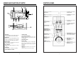
NAMES AND FUNCTION OF PARTS 3 4 5 CONTROL PANEL 6 Grill Auto cook Defrost 2 Defrost Combi Weighf Time M/W Lock Waff g Autocook Grill A Combi Power A 7 Auto Cook Menu Stop Clear More Less Tim Clock 1 9 e/W e ig h t Qua n fi t y 8 8 11 10 ¤ DOOR SEAL Door seal maintains the microwave within the oven cavity and prevents microwave leakage. ¤ CONTROL PANEL ¤ GLASS TURN -TABLE TRAY Rotates during cooking and ensure even distribution of Microwaves.
OPERATION HOW TO SET THE OVEN CONTROLS TO STOP THE OVEN WHILE THE OVEN IS OPERATING Tips : ¡ Be sure to read the cookbook’s introduction before operating the oven. ¡ Also remember to read this operating instruction for proper safety information and instruction before using t he oven. ¡ See the cookbook for specific recipes. ¡ Prior to setting the controls, place one cup of water in the oven, in a heat-proof glass measuring cup, for testing purposes.
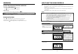
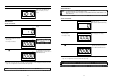
The display will show present time, and the colon starts blinking. This digital clock allows you to set to “10:10” 1. Press CLOCK button. WEIGHT DEFROST NOTE : • This digital weight allows you set from 200g to 3000g. • Whenever you press this button, the display is circulated WEIGHT DEFROST, TIME DEFROST , and MICROWAVE mode. SETTING THE CONTROL 1. Press DEFROST button once. TIME DEFROST The WEIGHT DEFROST indicator light will come on. The g indicator light will start blinking.
MICROWAVE GRILL NOTE : • To insure the best microwave and defrost results, be sure to start with a cool oven. Let the oven cool 15~20 minutes with the door slightly open. • Power levels are 900W, 700W, 500W, 350W, and 150W • It is displayed after an interval of 10 seconds from 10 seconds to 5 minutes, 30 seconds from 5 minutes to 10 minutes, 1 minute from 10 minutes to 99 minutes NOTE : • • • • • The heating element is located in the top of the oven. There is no pre-heating the oven for grilling.
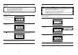
AUTO COOK TO SET COMBI COOKING NOTE : • Microwave and Gril operate simultaneously (or sequentially) in this mode. • Whenever you press COMBI button, display is changed “ : 0”, “ : H”, “ : L”, Therefore you can select power level of MICROWAVE NOTE : • There is programmed for cooking of nine kinds (1~9). • You don’t have to worry about setting time, power and function. 1. Press AUTO COOK button. SETTING THE CONTROL 1. Press COMBI button once again.
6. If you want to select other quantity, press quantity button once again until display you desired. SPEEDY COOK 1. Push button Then start lamp will start blinking. Whenever the button is pressed, cooking time is increased 30 seconds. If the time was setting, this oven is operated automatically after 2 seconds to microwave high power. 7.
INTERLOCK MECHANISM FUNCTIONS AND ADJUSTMENTS The door lock mechanism is a device which has been specially designed to completely eliminate microwave radiation when the door is opened during operation, and thus to perfectly prevent the danger resulting from the leakage of microwave. (2) Secondary interlock switchm, monitor interlock switch and D.O.
PRECAUTIONS FOR DISASSEMBLY AND REPAIR DISASSEMBLY AND ASSEMBLY - Cautions to be observed when trouble shooting. 1. To remove cabinet (Refer to Fig. 2) Unlike many other appliances, the microwave oven is high-voltage, high-current equipment. It is completely safe during normal operation. However, carelessness in servicing the oven can result in an electric shock or possible danger from a short circuit. You are asked to observe the following precautions carefully. 1) Remove four screws on cabinet back.
3. To remove lamp (Refer to Fig. 4) 5. To remove magnetron and magnetron thermostat (Refer to Fig. 6) F37 1) Remove a screw F37 holding lamp F36 to the guide air F34 2) Remove the lamp. 3) Reverse the above steps for reassembly. 1) Remove two secrews F26 which secure the thermostat 2) Remove the thermostat. 3) Remove three screws F24 which secure the magnetron 4) Remove the magnetron. 5) Reverse the above steps for reassembly. F36 F25. F23 . F34 FIG. 4 F26 F25 4. To remove H.V.
6. To remove parts of control panel assembly (Refer to Fig. 7,8) 1) Remove a screw holding control panel assembly to the oven front plate. At the same time, draw forward the control panel assembly from oven front plate. 2) Pull forward the knob volume B11 to take out B11 B12 B13 simultaneouly 3) Remove three screws B9 which secure the PCB main assembly B7 to control panel B1 . 4) Remove six screws B9 which secure the PCB sub assembly B6 to control panel B1 .
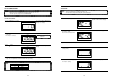
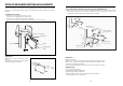
9. Method to reduce the gap between the door seal and the oven front surface. (1) To reduce gap located on part ‘A’. 1) Loosen a Hex Bolt on top door hinge, then push the door to contact the door seal to oven front surface. 2) Tighten a Hex Bolt. A 10. To remove tray motor (Refer to Fig. 11) D Defrost Combi Weighf Time M/W Grill Lock Auto cook Defrost Waff g Autocook Grill A Power Combi A 1) Cut the tray motor cover parts from the base plate (Refer to Fig 11, 12).
11. To remove grill heater assembly (Refer to Fig. 13) 1) Release three hex nuts F10 holding the Grill Heater Assembly 2) Remove Grill heater Assembly. (TROUBLE 1) Oven does not operate at all; any inputs can not be accepted F9 to top and side plate.
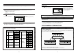
Condition Outlet has proper voltage. Fuse does not blow Check Result Check continuity both magnetron and heater thermostat No Continuity check continuity of noise filter board No Continuity Check continuity of power supply cord Cause Remedy Defective magnetron and heater thermostat Replace Defective line filter board Replace No Continuity Open power supply cord Normal Defective touch control circuit (TROUBEL 3) No microwave oscillation even though fan motor rotates.
(TROUBLE 4) Display shows all figures selected, but oven does not start cooking, even Condition Check Turn table motor, fan motor and oven lamp do not turn on Check continuity of primary interlock switch No Continuity Malfunction of primary interlock switch Adjust or replace Check continuity of secondary interlock and D.O.M. switch No Continuity Malfunction of secondary interlock and D.O.M. switch Adjust or replace Check D.C. voltage being supplied to RELAY (RY2) coil.
MEASUREMENT 1. Microwave Output Power CAUTION : 1-1. Standard Method Microwave output power can be checked by indirectly measuring the temperature rise of a certain amount of water exposed to the microwave as directed below. 1) Microwave power output measurement is made with the microwave oven supplied at rated voltage and operated at its maximum microwave power setting with a load of 1,000¡ 5cc of potable water.
COMPONENT TEST PROCEDURE WIRING DIAGRAM 1. High voltage is present at the high voltage terminal of the high voltage transformer during any cook cycle. 2. It is neither necessary not advisable to attempt measurement of the high voltage. 3. Before touching any oven components or wiring, always unplug the oven from its power source and discharge the capacitor (see page 20). 1. High voltage transformer 3. High voltage diode (A) Remove connections from the transformer terminals and check continuity.
SCHEMATIC DIAGRAMS IDLE GRILL M/W COMBI 38 39
WIRING DIAGRAM(GERMANY ONLY) SCHEMATIC DIAGRAMS (GERMANY ONLY) IDLE M/W 40 41
GRILL ƒN SUB : Substitutive REF NO. PART CODE PART NAME DESCRIPTION Q’TY F2 3510103700 CAVITY WELD AS KOG-8415 ØS 1 F5 3512504800 GUIDE WAVE SA1D-80 0.5T 1 F6 3510602500 BRACKET MAGNETRON SECC 1.2T 1 F7 3511401500 COVER WAVE GUIDE MICA 0.35T 1 F8 7113400814 SCREW TAPPING T1 BIN 4X8 MFNI 2 F9 3512800800 HEATER 1R07817 230V 1350W 1 F10 7S627W50X1 NUT HEX FLANGE M5X0.
EXPLODED VIEW 43
PRINTED WIRING BOARD ƒN SUB : Substitutive NO. PART CODE PART NAME DESCRIPTION F39 7121400811 SCREW TAPPING T2S PAN 4X8 MFZN 1 F40 3518902800 THERMOSTAT 130/120 H PW-2N 1 F41 7121400811 SCREW TAPPING T2S PAN 4X8 MFZN 1 F42 3512505000 GUIDE WIND P.P 1 F43 3963512910 MOTOR SHADED POLE 230V 25W MW15CA-K01 1 3963512900 Q’TY OEM-15DWC2-A02 1) Low voltage transformer (DMR-9940F) check. The low voltage transformer is located on the P.C.B.
3) Display problems NO. 1 2 3 CHECK METHOD CAUSE MEASUREMENT Poor contact between P.C.B and display filament. 1. Check the voltage of PIN 1 & PIN 25. The Display has some troubles in its segment or grid. Refer to “The display trouble shooting data” below. white spot Loss of vacuum in the display. RESULT REMEDY 2.6 VAC Fix the PIN 1 & 25 on the P.C.B. Replace P.C.B. assembly.
6) When the door is opened during operation, the count down timer does not stop. 1) Transistor(NPN Type) A D.O.M C8 S/W R10 BL 1 40 R11 BL Q1 ~ Q12 2 EARTH TERMINAL B -5V 3 -5V CN1 MICOM Emitter CHECK METHOD POINT STAGE 1) DOOR OPENED 2) DOOR CLOSED A B OPEN CLOSED -5VDC GND CHECK NO. METHOD Collector REMEDY Check the state (ON,OFF) of the secondary Interlock switch by resistance measurement.
P.C.B. LOCATION NO REF NO. PART CODE PART NAME DESCRIPTION REF NO. PART CODE PART NAME DESCRIPTION REMARK R4,5,12,13 RD-4Z102J- R CARBON FILM 1/4W 1KΩ J REMARK SW101~106 5S50101Z93 SWITCH KPT-1115AM PCB SUB R28, 34, 41 RD-4Z102J- R CARBON FILM 1/4W 1KΩ J EC1,2 CEXE1H100A C ELECTRO RS 50V 10µF 5X11 PT R27 RD-4Z101J- R CARBON FILM 1/4W 100Ω J EC3 CEXE1E101A C ELECTRO RS 25V 100µF 811.
DAEWOO ELECTRONICS CO., LTD. 686, AHYEON-DONG, MAPO-GU, SEOUL, KOREA C.P.O. BOX 8003 SEOUL, KOREA TELEX: DWELEC K28177-8 CABLE: “DAEWOOELEC” FAX: 02) 364-5588/5305 TEX: 02) 360-7114/7315~7 S/M NO.:G846T0S001 PRINTED DATE: FEB.