Service Instructions
Contents Dealer Pre-delivery Checklist .............................................................................03 VRO Stem ..................................................................................................................07 Flat Pak Stem ...........................................................................................................08 Handlepost Hinge ..................................................................................................10 Headset .................
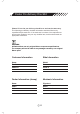
Dealer Pre-delivery Checklist Please fill out the pre-delivery checklist to activate the warranty. This following pre-delivery checklist information should be filled out by a qualified bicycle mechanic. If the mechanic is unclear of the requirements and process needed to carry out any checklist item, he/she should seek the appropriate assistance. WARNING: All Dahon bikes use only original Dahon component specifications. The company will not be liable for any damages caused by non-original Dahon parts.
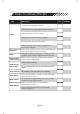
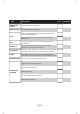
Dealer Pre-delivery Checklist Item Description OK The frame is not damaged or defective. All frame joints do not have physical defect or damage. Frame Main hinge(s) opens and closes freely. Main hinge(s) is not obstructed when locked. Main hinge safety latch functions properly. Magnetix holding latches are securely tightened in front and rear of bicycle. Drivetrain Pedal, cranks, chainrings, bottom bracket and derailleur(s) are securely fastened and correctly aligned.
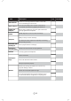
Item Description OK Brake Blocks Blocks are correctly positioned to make contact with the rim. Retaining nuts are secure. Brake Calipers Front and rear calipers are correctly centered; they are smooth and effective in gripping the wheel rim. Saddle and seatpost All seat bolts, saddle bolts, and seat quick releases are correctly tightened and adjusted. Saddle Saddle alignment is correct (forward and level). Ability to fold your frame efficiently.
Dealer Pre-delivery Checklist Item Wheel quick release Description OK Correctly installed and adjusted. Wheel bearings Correctly installed and adjusted. Tires Free of physical damage or defect; properly positioned and facing the correct direction. Have the correct air pressure; dust cap can be located on the valves. Bell Check that the bell is present and securely fastened to the handlebar. Reflectors Check that both reflectors are present and securely fastened to your front and rear wheels.
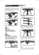
VRO Stem With a VRO clamp, the handlebar can be easily adjusted to fit the rider’s height or desired riding position by simply moving it up and down, forward and backward. The following instructions explain how to adjust the VRO clamp. Step 2 -Using a 5mm Allen key, loosen the bolts of theVRO clamps. Step 3 - Adjust the height and position of the handlebar to attain your preferred riding position. Move the VRO clamp within the window of adjustment - front, backwards, up and down.
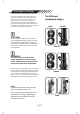
Flat Pak Stem The newly developed Flat Pak stem allows easy adjustment of the handlebar in any direction through two quick-release levers. By adjusting the handlebar's angle, riders can change their riding position; whether upright for leisurely riding, or forward for more competitiveness. The Flat Pak stem also rotates 90° to save room in tight spaces.
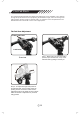
Flat Pak Stem Continued To achieve your preferred riding position, you can adjust the height and position of the Flat Pak stem. Here are some suggested riding positions: High City position Step 3 - Lift front lock lever and rotate handlebars to desired position. While establishing your perferred riding position, check to see that the handlebar is readjusted in the right position. The correct angle of the handlebars should allow the fingers to reach the brake levers.
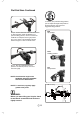
Handlepost Hinge The Different Handlepost Hinges On Dahon folding bicycles, the handle-post hinge latch should be checked before each ride to ensure that it closes properly for the handle-post to remain secure. A closed handle-post hinge with a properly adjusted and secured latch should not have side-to-side movement. Periodically, inspect the handle-post to ensure that it is properly adjusted. OPEN CLOSED CAUTION: Do not attempt to ride your bicycle with a loose handlepost hinge.
Adjusting the Handlepost Hinges NOTE: To avoid over tightening or loosening the hinge, make adjustments in small(1/16) increments. NOTE: If the hinge is very tight, please clear off dirt and add lubricating oil. Radius V - to make adjustments, use a 6mm wrench to tighten or loosen. An adjustable wrench or small pliers can also be used if a 6mm wrench is not available. LOOSEN: TIGHTEN: Follow the arrows on which way to turn the latch bolt. Follow the arrows on which way to turn the latch bolt.
Headset Periodically check your headset. If the handlepost should ever feel too loose, or you have noticed there is an abundant amount of movement in the fork, the headset may need to be adjusted. A properly adjusted headset eliminates the possibility of movement, while still allowing the handlebars to be turned. The following instructions explain how to adjust the headset. WARNING: Step 1 - Open the handlepost clamp as indicated above, using a 6mm Allen key counter-clockwise.
Telescope stem A telescope stem allows for convenient adjustment of the handlebar height. Operation is exlained in the steps below. Red mark point Safety line Step 1 Open quick release (MIN.INSERTION) WARNING: Do not extend the telescope stem beyond the safety line when adjusting handlebar height. Check that the safety line is not visible before riding.
Frame Latch The most important part of a folding bicycle is frame hinge. Special care should be taken to check that the hinge is adjusted correctly before each ride. Tools Needed: • 10 mm wrench • 6 mm Allen key Your frame hinge will need occasional adjustments from time to time. If the hinge ever becomes too loose it may need to be adjusted. Properly adjusting the hinge will eliminate movement or looseness.
The V-Clamp Hinge There are a several versions of the V-Clamp. Learn how to adjust the V-Clamp with the instructions provided below. Check your bike to determine which V-Clamp version is being used and apply the appropriate instructions to the correct V-clamp version. Adjust the hinge bolt to allow the hinge to open and close with the same amount of force (39~88 Nm). NOTE: While adjusting a V-Clamp hinge, turn in increments of 1/16 for the best result in securing the hinge.
Adjust the hinge bolt to allow the hinge to open and close with the same amount of force (39~88 Nm). NOTE: While adjusting a V-Clamp hinge, turn in increments of 1/16 for the best result in securing the hinge. Failure to effectively adjust the hinge could result in the hinge being too tight or too loose. WARNING: If the hinge is too tight, it could cause tension and damage to the frame.
Adjust the hinge bolt to allow the hinge to open and close with the same amount of force (39~88 Nm). NOTE: While adjusting a V-Clamp hinge, turn in increments of 1/16 for the best result in securing the hinge. Failure to effectively adjust the hinge could result in the hinge being too tight or loose. WARNING: If the hinge is too tight, it could cause tension and damage to the frame. VERSION C* *TOOLS NEEDED: 10 mm wrench, 6 mm Allen key Step 1 - To loosen the Lock Nut: Use a 10mm wrench.
LockJaw Hinge Adjustment Overview Bikes equipped with the LockJaw hinge look like your average bike. In order to see the LockJaw, pinpoint where the bike folds. Read the following directions carefully to ensure safety when using the LockJaw hinge with your bike. There are two versions of the LockJaw available. Check your bike to determine which LockJaw version is used and apply the appropriate instructions.
Open/Close the LockJaw Hinge Use a 6 mm Allen key. Please refer to the folding instructions that were included with your bicycle on how to properly fold a LockJaw equipped bicycle. Turning the OC bolt counter-clockwise 180° will allow the LockJaw hinge to unlock. See picture above. To lock the LockJaw hinge, simply close the hinge and turn the OC bolt clockwise 180°. If you properly adjust the adjustment bolt, you should feel a slight “click.” The teeth of the LockJaw hinge will come together.
Adjust the Tightness of the LockJaw (The Adjustment Bolt) Adjust the Adjustment Bolt while the frame is closed. The LockJaw is exceptionally secure,but will require periodic inspection and adjustment to ensure that it is properly working. Adjust the LockJaw according to the following instructions. Version A Do not over-loosen the adjustment bolt TIGHTEN Tools Needed: • 6mm Allen key NOTE: Only turn the adjustment bolt in small increments (e.g.
Adjust the Adjustment Bolt while the frame is closed. Version B Tools Needed: • 6mm Allen key • 2.5mm Allen key NOTE: Only turn the adjustment bolt in small increments (e.g. an 1/8 turn) each time, otherwise it could result in too much constriction and/or movement. Do not put too much force on the adjustment bolt.
Index Shifting Adjustment WARNING: If you are unsure of how to make proper adjustments to your bicycle, seek a qualified bicycle technician for professional advice on adjustments. Step 1 - Open the lock screw using a 2mm Allen key. When the LockJaw is unlocked, the frame is able to rotate around the pivot bolt. Follow the instructions to adjust (loosen/ tighten) the pivot bolt. At times, it might be difficult to rotate the frame due to the pivot bolt being too tight.
Kore I-Beam The Kore I-beam is a ground-breaking new saddle system. As well as dramatically cutting down weight, the system allows the rider to achieve maximum saddle adjustability. The saddle can be moved forward and backward on the rail, while the tilt can be adjusted up or down. Tools Needed: • 4mm Allen key Step 3 - Adjust the tilt of the saddle. Step 1 - With a 4mm Allen wrench, loosen the Kore I-beam seat rail clamp Step 4 - Adjust the fore and aft position. Step 2 - Fit the saddle to the rails.
Seatpost Your seatpost is secured by a quick release that allows for easy height adjustment to the proper and most comfortable height. Step 1 Open quick release Step 2 Move saddle to proper position WARNING: Do not adjust the seatpost height beyond the Min Insertion or Max Insertion lines. Remember to check that the position is inbetween these safety markers before riding.
Dahon Neos Derailleur The low-profile Dahon Neos derailleur was specially designed for small-wheeled bicycles. The Neos allows much more ground clearance than a conventional derailleur. Using cache technology, it permits the derailleur body to lie flat underneath the chain stays. This way the derailleur body only projects 12mm from the chain stays and is much more protected than a standard derailleur, which protrudes up to 40mm.
High Adjustment When looking from the rear, turn the top adjustment screw to align the guide pulley with and below the outer line of the smallest sprocket. Low Adjustment Turn the low adjustment screw for the guide pulley to move directly in-line with the largest sprocket.
Index Shifting Adjustment While turning the crank arm, use the shifter to move the derailleur to the largest sprocket. Operate the shifter once more to move the derailleur to the 2nd-gear sprocket. Operate the shifter to the point of movement, and then turn the crank arm. Best Setting For the best possible outcome, tighten the cable adjustment bolt (clockwise) until you hear a noise that occurs without harming the shifter being operated. Proceed to loosen (counter-clockwise) 360 degrees.
Service Instructions Headquarters Dahon North America INC. 833 Meridian Street Duarte CA 91010 +1 800 442 3511 www.dahon.com Dahon Technologies, Ltd. Dahon Bldg, Furong 6th Rd., Shajing Shenzhen, 518125, P.R.C +86 755 27249136 Dahon Europe No.1 P.O. Box 17, Goliamokonarsko Shosse Str.