English Français INSTALLATION MANUAL R410A Split Series Español DAIKIN ROOM AIR CONDITIONER Installation manual Manuel dinstallation Manual de instalación MODELS RX30NMVJU RX36NMVJU RK30NMVJU RK36NMVJU 00_CV_3P457793-1.
Contents Safety Considerations ..................................... 1 4. Refrigerant piping......................................................... 6 5. Pressure test and evacuating system........................... 7 Accessories ...................................................... 3 6. Refilling refrigerant....................................................... 8 7. Refrigerant piping work ............................................... 8 Precautions for Selecting a Location ............
• Make sure that all wiring is secured, that specified wires are used, and that no external forces act on the terminal connections or wires. Improper connections or installation may result in fire. • When wiring, position the wires so that the electrical wiring box cover can be securely fastened. Improper positioning of the electrical wiring box cover may result in electric shock, fire, or the terminals overheating. • Before touching electrical parts, turn off the unit.
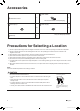
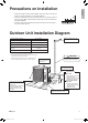
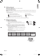
Accessories B Drain socket* A Installation manual 1 1 This is at the bottom of the packaging. C Drain cap (1)* D Drain cap (2)* 6 E Warranty 1 3 *Only for heat pump models. Precautions for Selecting a Location 1) Choose a place solid enough to bear the weight and vibration of the unit, where the operating sound will not be amplified. 2) Choose a location where the hot air discharged from the unit or the operating sound will not cause a nuisance to the neighbors of the user.
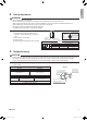
English Precautions on Installation 3/4” (20mm) • Check the strength and level of the installation surface so that the unit does not cause any operating vibrations or noise after installation. • Fix the unit in place securely using foundation bolts, as in the figure. (Prepare 4 sets of 5/16 inch (M8) or 3/8 inch (M10) foundation bolts, nuts and washers; all separately available.) • It is best to screw in the foundation bolts until their ends are 3/4 inch (20mm) from the foundation surface.
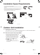
Installation Space Requirements • Position the unit on a horizontal surface. Any tilt in the unit (front to back, right to left) should be 3° or less to the horizontal. • Where a wall or other obstacle is in the path of the outdoor unit’s intake or exhaust airflow, follow the installation space requirements below. • For any of the below installation patterns, the wall height on the outlet side should be 47-1/4 inch (1200mm) or less.
English 3. Flaring the pipe end WARNING • • • • • • Do not apply mineral oil to the flare. Prevent mineral oil from getting into the system as this would reduce the service life of the units. Never use piping which has been used for previous installations. Only use parts which are delivered with this unit. Never install a dryer to this R410A unit in order to guarantee its service life. The drying material may dissolve and damage the system. Incomplete flaring may result in refrigerant gas leakage.
Outdoor Unit Installation 5. Pressure test and evacuating system WARNING • • • • Make sure that air or any matter other than refrigerant (R410A) does not get into the refrigeration cycle. If refrigerant gas leaks should occur, ventilate the room as soon and as much as possible. R410A, as well as other refrigerants, should always be recovered and never be released directly into the environment. Use a vacuum pump for R410A exclusively.
English 6. Refilling refrigerant Check the type of refrigerant to be used on the machine nameplate. Precautions when adding R410A Fill from the liquid pipe in liquid form. R410A is a mixed refrigerant, so adding it in gas form may cause the refrigerant composition to change, preventing normal operation. 1) Before filling, check whether the cylinder has a siphon attached or not. (It should have something like “liquid filling siphon attached” displayed on it.
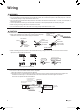
Wiring WARNING • Do not use tapped wires, extension cords, or starburst connections, as they may cause overheating, electric shock, or fire. • Do not use locally purchased electrical parts inside the product. (Do not branch the power for the drain pump, etc., from the terminal block.) Doing so may cause electric shock or fire. • The circuit must be protected with safety devices in accordance with local and national codes, i.e. a fuse, a circuit breaker, a disconnect or a GFCI.
English [Method of mounting conduit] 1) Dismount the service lid by removing the 2 screws. 2) Pass wires through the conduit and secure them with a lock nut. 3) After completing the work, reattach the service lid to its original position. Power supply terminal block 1 2 3 Shape wires so that the conduit mounting plate fits securely. L1 L2 Service lid Screws Conduit mounting plate Lock nut ■English 01_EN_3P457793-1.
Facility Setting (cooling at low outdoor temperature) WARNING Make sure to turn the power OFF before removing the service lid. CAUTION • If the outdoor unit is installed where the heat exchanger of the unit is exposed to direct wind, provide a windbreak wall. • Intermittent noises may be produced by the indoor unit due to the outdoor fan turning on and off when using facility settings.
In order to protect the environment, be sure to pump down when relocating or disposing of the unit. 1) 2) 3) 4) 5) Remove the valve cap from the liquid stop valve and gas stop valve. Carry out forced cooling operation. After 5 to 10 minutes, close the liquid stop valve with a hexagonal wrench. After 2 to 3 minutes, close the gas stop valve and stop forced cooling operation. Attach the valve cap once procedures are complete.
Two-dimensional bar code is a manufacturing code. 3P457793-1 M16B120 (1611) 00_CV_3P457793-1.