
Installation manual
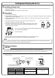
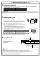

Refrigerant Piping Work (3)
Wall
If no flare cap is
available, cover
the flare mouth
with tape to keep
dirt or water out.
Be sure to
place a cap.
Rain
Gas pipe
Liquid pipe
Gas pipe
insulation
Liquid pipe
insulation
Finishing tape
Drain hose
Inter-unit wiring
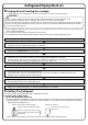
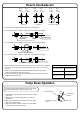
8 Flaring the Pipe End
1)Cut the pipe end with a pipe cutter.
2)Remove burrs with the cut surface facing downward
so that the chips do not enter the pipe.
3)Put the flare nut on the pipe.
4)Flare the pipe.
5)Check that the flaring is properly made.
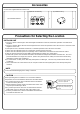
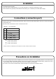
Outdoor unit capacity class
Total length of piping for all rooms
4MXS32∗
131.2ft
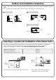
6 Charging with Refrigerant
● If the total length of piping for all rooms exceeds the figure listed below, additionally charge with 0.22oz of
refrigerant (R410A) for each additional feet of piping.
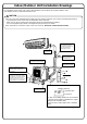
7 Refrigerant Piping Work
Cautions on Pipe Handling
1)Protect the open end of the pipe against dust and moisture.
2)All pipe bends should be as gentle as possible. Use a pipe bender for
bending. (Bending radius should be 1-3/16 to 1-9/16 inch or larger.)
Selection of copper and heat insulation materials
When using commercial copper pipes and fittings, observe the following:
1)Insulation material: Polyethylene foam
Heat transfer rate: 0.041 to 0.052W/mK (0.024 to 0.030 Btu/fth°F)
Refrigerant gas pipe’s surface temperature reaches 230°F max.
Choose heat insulation materials that will withstand this temperature.
2)Be sure to insulate both the gas and liquid piping and to provide
insulation dimensions as below.
3)Use separate thermal insulation pipes for gas and liquid refrigerant pipes.
Even though the stop valve is fully closed, the refrigerant may slowly leak out; do not leave the flare nut removed for
a long period of time.
CAUTION
1) Do not use mineral oil on flared part.
2) Prevent mineral oil from getting into the system as this reduces the lifetime of the units.
3) Never use piping used for previous installations. Only use parts that are delivered with the unit.
4) Never install a drier to this R410A unit in order to guarantee its lifetime.
5) The drying material may dissolve and damage the system.
6) Incomplete flaring may cause refrigerant gas leakage.
WARNING
(Cut exactly at
right angles.)
Remove burrs
Check
Flare’s inner surface
must be flaw-free.
The pipe end must be evenly
flared in a perfect circle.
Make sure that the flare
nut is fitted.
Pipe size
O.D.: 1/4” / Thickness: 0.030”
O.D.: 3/8”, 1/2” / Thickness: 0.030”
O.D.: 5/8” / Thickness: 0.040”
Pipe insulation
I.D.: 3/8-5/8” / Thickness: 3/8” min.
I
.D.: 1/2-5/8” / Thickness: 1/2” min.
I.D.: 5/8-3/4” / Thickness: 1/2” min.
Set exactly at the position shown below.
A
Flaring
Die
A 0 ~ 0.020”
Clutch-type
Flare tool for R410A
0.039 ~ 0.059”
Clutch-type (Rigid-type)
0.059 ~ 0.079”
Wing-nut type (Imperial-type)
Conventional flare tool