USE AND MAINTENANCE MANUAL SAR 440 SA GDS 01/2006 THOMAS S.p.A. - Via Pasubio, 32 - 36033 Isola Vicentina (VI) - Telephone 0444 / 97.61.05 - Fax 0444 / 97.69.34 Registro Imprese n. 4272//VI116 REA n.
SAR440SAGDS Contents Contents ........................................................................... " Ordering spare parts ........................................................ " Guarantee ........................................................................ " Machine certification and identification marking ............. " CHAPTER 1 Reference to accident-prevention regulations .................. " 1.1 - Advice for the operator ............................................. " 1.
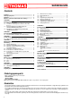
SAR440SAGDS Machine certification and identification marking MACHINE LABEL via Pasubio, 32 36033 ISOLA VIC.
SAR440SAGDS 1 REFERENCE TO ACCIDENT - PREVENTION REGULATIONS This machine has been built to comply with the national and community accident-prevention regulations in force. Improper use and/or tampering with the safety devices will relieve the manufacturer of all responsibility. 1.1 - Advice for the operator - Check that the voltage indicated on the plate, normally fixed to the machine motor, is the same as the line voltage.
SAR440SAGDS 1.3 - Electrical equipment according to European Standard "CENELEC EN 60 204-1" which assimilates, with some integrating modifications, the publication "IEC 204-1" - The electrical equipment ensures protection against electric shock as a result of direct or indirect contact. The active parts of this equipment are housed in a box to which access is limited by screws that can only be removed with a special tool; the parts are fed with alternating current at low voltage (24 V).
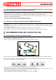
SAR440SAGDS 3 TECHNICAL CHARACTERISTICS 3.1 - Table of cutting capacity and technical details 4 MACHINE DIMENSIONS TRANSPORT INSTALLATION DISMANTLING 0° 440 440 610 x 440 45° DX 440 440 500 x 230 45° SX 440 440 500 x 230 60° DX 320 300 320 x 245 60° SX 340 320 340 x 250 2500 4.
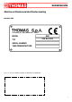
SAR440SAGDS - Position the machine on a firm cement floor, maintaining, at the rear, a minimum distance of 1000 mm from the wall; anchor it to the ground as shown in the diagram, using screws and expansion plugs or tie rods sunk in cement, ensuring that it is sitting level. 4.
SAR440SAGDS eral is in a state of continuous evolution and therefore subject to changes and variations, the user must keep informed of the regulations in force at the time of disposing of the machine tool, as these may differ from those described above, which are to be considered as a general guide line. 5 MACHINE FUNCTIONAL PARTS 5.
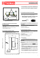
SAR440SAGDS 6 160 BAR DESCRIPTION OF THE OPERATING CYCLE Before operating, all the main organs of the machine must be set in optimum conditions (see the chapter on “Regulating the machine”). 6.1 - Getting started DESCRIPTION OF THE CUTTING PROCESS: - Start the cutting cycle Automatic closure of the vice; Lowering of the sawframe ( blade ); Lifting of the sawframe ( using selector ); Opening of the vice.
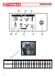
SAR440SAGDS 2 3 9 1 4 10 5 6 1 F VOLANTINO VARIATORE VARIATOR - HAND WHEEL 8 9 27.5 32 10 11 12 13 14 15 16 17 18 19 20 21 22 23 24 25 26 27 28 46 51 56 61 66.5 72 77.5 83 89 95 101 107 113 120 127 133 140 POS. N° VELOCITA' DI TAGLIO CUTTING SPEED m/min 10 36.5 41.
SAR440SAGDS - the CUTTING SPEED and the TYPE of BLADE - combined with a suitable lowering of saw frame - are of decisive importance for cutting quality and for machine performance (for further details on this topic, see below in the chapter on “Material classification and blade selection”).
SAR440SAGDS 7.5 - 7.3 - Vice -- The rapid advancement of the vice to the object to be cut is obtained by manually moving the vice and lifting the latch ( F ). Before blocking the object to be cut with the hand wheel check that the latch is gripped to the rack. - The vice unit can be positioned to the left or right of the blade. Ensure that this positioning has been executed correctly in order to avoid irreparable damage to the saw.
SAR440SAGDS BEFORE PERFORMING THE FOLLOWING OPERATIONS, THE ELECTRIC POWER SUPPLY AND THE POWER CABLE MUST BE COMPLETELY DISCONNECTED. 7.8 – Replacing the blade - Lift the sawframe in upright position. - Loosen the blade with the hand wheel, remove the shield of the mobile blade guide and the shield of the belt cleaning brush. - Open the posterior and anterior carter flywheels and extract the old blade from the flywheels and from the blade guide blocks.
SAR440SAGDS 9 MATERIAL CLASSIFICATION AND CHOICE OF TOOL Since the aim is to obtain excellent cutting quality, the various parameters such as hardness of the material, shape and thickness, transverse cutting section of the part to be cut, selection of the type of cutting blade, cutting speed and control of saw frame lowering.
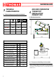
SAR440SAGDS SOLID Ø OR L MM Z CONTINUOUS TOOTH DESIGN Z COMBO TOOTH DESIGN TILL 30 8 5/8 FROM 30 TO 60 6 4/6 FROM 40 TO 80 4 4/6 MORE THAN 90 3 3/4 9.7 - Blade type They differ essentially in their constructive characteristics, such as: - shape and cutting angle of tooth - pitch - set Shape and angle of tooth Ø = DIAMETER L = WIDTH REGULAR TOOTH: 0° rake and constant pitch. 9.
SAR440SAGDS the cutting of pipes and thin section bars (from 1 to 3 mm). Set Saw teeth bent out of the plane of the saw body, resulting in a wide cut in the workpiece. REGULAR OR RAKER SET: Cutting teeth right and left, alternated by a straight tooth. Of general use for materials with dimensions superior to 5 mm. Used for the cutting of steel, castings and hard nonferrous materials. WAVY SET: Set in smooth waves.
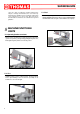
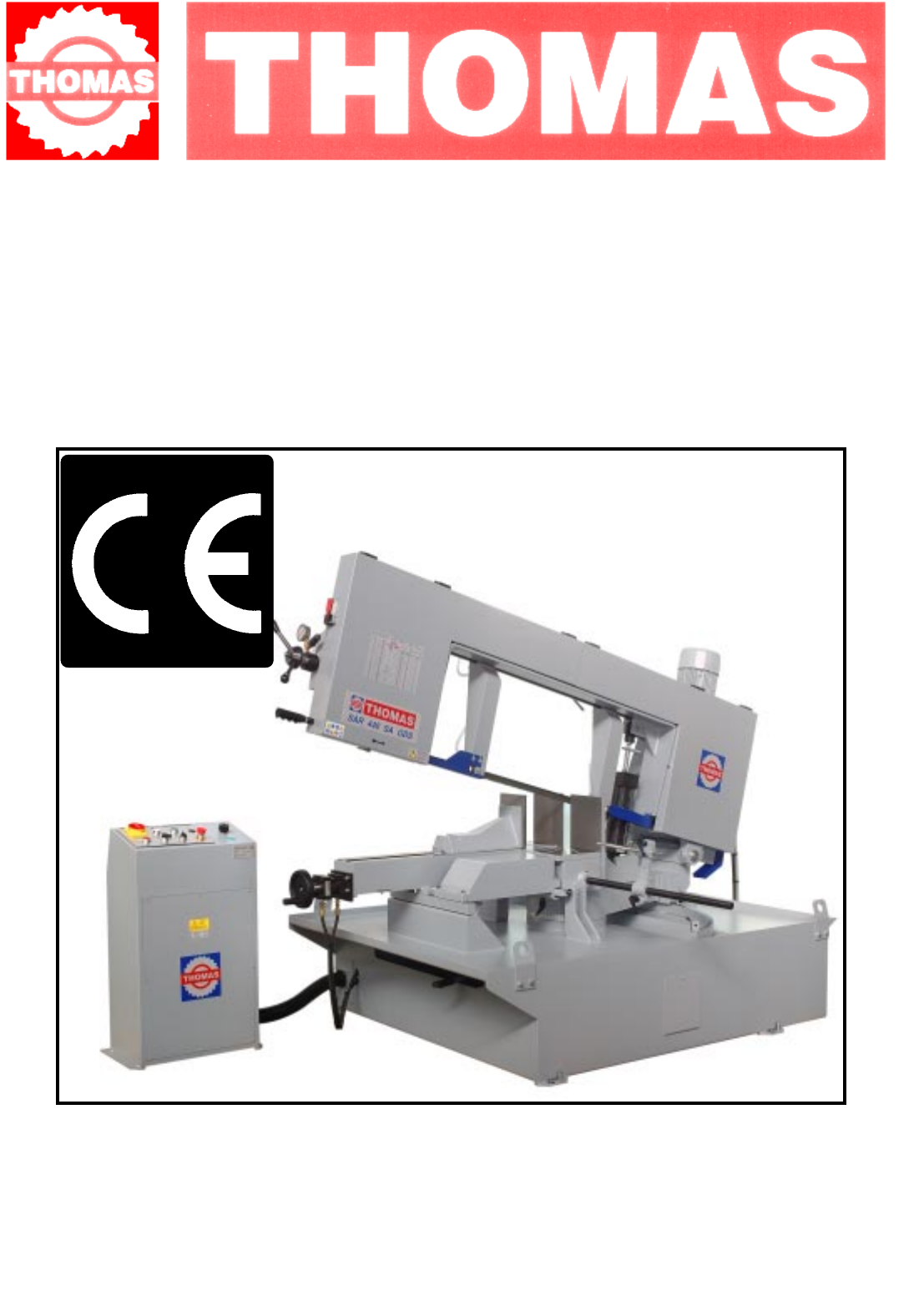
SAR440SAGDS 10 MACHINE COMPONENTS 10.
SAR440SAGDS REFERENCE N° DENOMINATION REFERENCE N° DENOMINATION 60 61 62 63 64 65 66 67 68 69 70 71 72 73 74 75 76 77 78 79 80 81 82 Sawframe Electric motor Speed variator Speed variator handwheel Ring nut guk M 40x1,5 Speed reducer Spacer 107 108 109 110 111 112 113 114 115 116 117 118 119 120 121 122 123 124 125 126 127 Spacer Bearing 51204 Spring washer Manometer Pressure switch Rear crucible 83 84 85 86 87 88 89 90 91 92 93 94 95 96 97 98 99 100 101 102 103 104 105 106 18 Cylinder joint Cylind
38 39 36 48 41 3 37 33 2 35 34 30 31 54 29 28 27 50 1 9 26 20 4 8 17 24 22 51 16 19 43 21 52 5 15 46 44 53 6 14 18 8 45 13 47 43 23 49 7 12 11 25 6 10 42 SAR440SAGDS 19
132 134 ZOOM - 2 133 131 131 130 61 70 63 71 64 68 77 112 73 78 109 108 82 69 98 65 91 107 92 93 94 95 96 85 81 66 76 75 110 60 62 72 84 111 86 101 87 98 83 89 87 86 120 90 100 SAR440SAGDS 135
SAR440SAGDS 104 103 104 102 124 126 125 106 123 122 121 114 97 117 115 114 117 116 118 ZOOM 2 115 118 116 ZOOM 1 21
SAR440SAGDS 406 401 408 405 402 403 KEY: 401 402 403 404 405 406 407 408 Main switch Arch movement selector Emergency switch STOP button Regulator arch descent On-line button Start button Vice selector 1 404 407 KEY: 410 411 412 413 414 415 416 417 Transformer Fuse cartridge Relay ( Kb ) Remote switch Thermal motor Remote switch Timer Thermal motor 411 413 417 414 415 410 KEY: 421 422 423 424 Motor gear case id. Vice electrovalve-solenoid Gear case tank id.
SAR440SAGDS 11 ELECTRIC DIAGRAM THOMAS THOMAS 11.1 - Three-phase electric diagram QS1 FU1 KM1 KM2 FR2 Main switch Fuse cartridge Central motor control switch id. Motor belt control switch Thermal motor belt M1 M2 M3 FU2 TC1 Motor gear case id.
THO MAS THOMAS SAR440SAGDS 24
SAR440SAGDS 11.2 - Hydraulic electric diagram 01 Sawframe downfeed regulator 02 Sawframe lifting speed regulator 04 Electric valve 05 Valve 06 Valve E L E N C O C O M P O N E N T I E L E T T R IC I M O D .: R IF .
SAR440SAGDS 12 TROUBLESHOOTING This chapter lists the probable faults and malfunctions that could occur while the machine is being used and suggests possible remedies for solving them. The first paragraph provides diagnosis for TOOLS and CUTS, the second for ELECTRICAL COMPONENTS. 12.1 - Blade and cut diagnosis FAULT PROBABLE CAUSE REMEDY TOOTH BREAKAGE Too fast advance Decrease advance, exerting less cutting pressure. Adjust the braking device if mounted on the machine.
SAR440SAGDS FAULT PROBABLE CAUSE REMEDY PREMATURE BLADE WEAR Faulty running-in of blade See “Material classification and blade selection” in the Blade running-in section. Turn teeth in correct direction.
SAR440SAGDS FAULT PROBABLE CAUSE REMEDY Blade guide pads not regulated or dirty because of lack of maintenance Check distance between blocks (see “Machine adjustments” in the Blade Guide Blocks section): extremely accurate guiding may cause cracks and breakage of the tooth. Clean carefully.
SAR440SAGDS FAULT PROBABLE CAUSE REMEDY Broken teeth Irregular work of the blade due to the lack of teeth can cause deflection in the cut; check blade and if necessary replace it. Check level of liquid in the tank. Increase the flow of lubricating refrigerant, checking that the hole and the liquid outlet pipe are not blocked. Check the emulsion percentage.
SAR440SAGDS 12.2 - Electrical components diagnosis FAULT PROBABLE CAUSE REMEDY MACHINE DOES NOT WORK Power supply Check: Main disconnect switch Fuses " FU 1 " " SQ 1 " safety microswitch Blade tightening microswitch Emergency button " SB 1 " on Cycle reset or line button " SB 2 " Thermal relay of main motor Transformer " TC 1 " Fuse " FU 2 - FU 3 " MOTOR STOPPED WITH PILOT LIGHT “HL” LIT Check that the supply voltage is the same as the line voltage and that it gives a value of 24 V at output.
SAR440SAGDS PLATES AND LABELS 31
THOMAS S.p.A. - Via Pasubio, 32 - 36033 Isola Vicentina (VI) - Telephone 0444 / 97.61.05 - Fax 0444 / 97.69.