Dakota Digital SERIES II VFD DIGITAL INFORMATION SYSTEM The latest in digital technology for the motorcycle enthusiast. INSTALLATION AND OPERATION MANUAL Please read this before beginning installation or wiring. MODEL HLY-2000 SPEEDOMETER/TACHOMETER INFORMATION SYSTEM Dakota Digital 4510 W 61st Street North.
POWER Connect the red wire from the main harness to accessory power from the ignition switch. In addition to powering the display system, this is also where the low voltage detection circuit monitors the electrical system voltage. A good quality, solid state ignition switch should be used. The contacts on a mechanical “bar” switch can bounce due to the vibration and cause the system to momentarily loose power and reset itself. Never connect this to a battery charger alone.
TACHOMETER The tachometer is used by connecting the yellow wire from the main harness to the negative side of the coil or to an ignition module tach output. The tachometer is adjustable for 1, 2, or 8 cylinder settings. The 1 cylinder setting is used for single-fire ignition systems without a buffered tach output. The following instructions are used to set the tachometer calibration: 1. Make sure the key is off so the gauge is not powered. 2. Press and hold the function switch. 3.
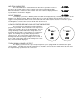
NEUTRAL INDICATOR The neutral indicator is activated when the blue wire is grounded. Connect this wire to the neutral switch or to the negative side of the neutral indicator light. When the indicator is activated, a bar on either side of the odometer display will move up and down as shown in the diagram. NIGHT DIMMING Your display system has a dimming feature that dims the display intensity. Normally the system is at full brightness for daytime viewing.
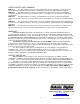
WIRING In order to ensure that there are no problems with voltage drops causing the system to shut down, a heavy duty, solid state ignition switch is recommended. Also, the black wire should be connected directly to the negative battery terminal to avoid erratic operation due to a poor ground connection. A complete description of the hookup for each wire is discussed in the previous sections of the installation manual. The typical color code for the stock wiring harness is provided to help in wiring.
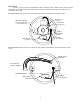
MOUNTING The base system is universal enough to fit in either a new-style, clip-in (1995 or newer) or into the older style, bolt-in. The rubber mounts with studs on both sides are used for the bolt-in style. The L-brackets are used for the clip in style. Mounting hardware and speed sensor connection for the bolt-in system with a speedometer cable. Speed Sensor Connector Attach the foam tape to the case just below the chrome bezel.
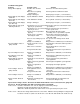
Troubleshooting guide. Problem Gauge will not light up Gauge lights up, but displays “SPd” “Err” Gauge lights up, but displays “tCH” “Err” Gauge lights up, but displays just “Err” only Gauge lights up, but speed will only show zero. Speed reading is erratic or jumps around. Speed reading is incorrect. Speedometer reads “255” while driving. Gauge lights up, but tach will only show zero. Tach reading is erratic or jumps around. Tach reading is incorrect. Gauge remains dim at all times.
SPEED ADAPTER PART NUMBERS SEN-2011: The cable adapter accepts a 5/8” thread fitting and can be mounted in a concealed location. Cycles that have a metric-threaded speedometer cable will need to have the cable modified or replaced. SEN-2012: The adapter harness for using a stock transmission speed sensor converts the triangular connector to the in-line connector on the speed/tach system. 18” length for speed connectors located by the speedometer.