
Installation manual
5
WIRING
In order to ensure that there are no problems with voltage drops causing the system to shut down, a
heavy duty, solid state ignition switch is recommended. Also, the black wire should be connected directly to the
negative battery terminal to avoid erratic operation due to a poor ground connection.
A complete description of the hookup for each wire is discussed in the previous sections of the
installation manual. The typical color code for the stock wiring harness is provided to help in wiring. Dakota
Digital does not guarantee that this is correct for all models and should only be used for reference. Not all wires
will be found in all bikes. Some bikes may have the same color wire used in more than one place. The wire
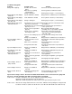
color code for the main display system harness is as follows:
HLY-2000 Stock harness color Function
RED ORANGE/WHITE +12 volt with key on
BLACK BLACK ground (connect directly to battery negative)
ring terminal connect to a case mounting screw
YELLOW PINK tachometer signal
PURPLE WHITE high beam indicator
ORANGE VIOLET left turn indicator
GREEN BROWN right turn indicator
BLUE TAN neutral indicator
GRAY GREEN/YELLOW oil warning indicator
WHITE/BLUE use supplied switch function (trip select/reset) switch
WHITE WHITE/GREEN output speed signal
BROWN normally not used night dimming
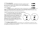
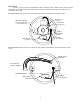
Speedometer connection varies depending on the year and model of the cycle. Using different speed
adapter kits the speedometer can read a speedometer cable, a stock electric transmission speed sensor, or an
aftermarket gear-tooth sensor. Each adapter kit connects to the speedometer using the three pin connector on
the bottom of the system.
The cable adapter accepts a 5/8” thread fitting and can be mounted to the bottom of the system using
the supplied bracket or remote mounted. Cycles that have a metric-threaded speedometer cable will need to
have the cable modified or replaced.
The adapter harness for using a stock transmission speed sensor converts the triangular connector to
the in-line connector on the speed/tach system.
The gear-tooth sensor kit consists of a two-terminal sensor and a harness to connect it to the
speed/tach system. The sensor needs to be mounted within 1/8” of the teeth on a final drive gear.