
Service manual
MAN 650314:D
9
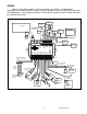
SPD –
This terminal is used for speed sensor ground. The wire color is BLACK on a 3-wire
sensor. This insures a proper ground as well as providing proper hook-up for a twisted pair of
wires, or a solid state sensor. Only ground the speed sensor here. If you are using a single wire
output from a computer for the VSS then this terminal should be left open.
SPD OUT
This terminal can be used to supply a speed signal to auxiliary devices such as a cruise
control or radio volume adjustment. The output is scaled to the input speed signal coming into
the SPD SND terminal. It can be set to 2,000 PPM or 4,000 PPM.
***If you are using the BIM-01-1 bus speed signal option this output will NOT work.
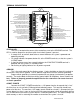
SW2 (-) or Tach switch
The SW2 terminal is used for selecting the various RPM, engine, and performance
displays and also for entering the demonstration mode. The SW2 input is activated by a ground
connection. The push button switch supplied (or any normally open, momentary switch) is wired
by connecting one wire to SW2 and the other wire to a ground. When the button is pressed and
released, the tach/LCD2 message display will change. When the button is pressed and held for a
few seconds, any re-settable information displayed will be zeroed.
To enter DEMO mode, press and hold SW2 while turning the key on. The system will light
up and say DAKOTA DIGITAL on the message readouts; release the switch and the system will
stay in demo mode until the power is cycled off and back on without the switch held. All back
lights will be on in demo mode and the needles will sweep back and forth on the gauges.
SW1 (-) or Speed switch
The SW1 terminal is used for selecting the various speed, distance, and warning displays
and also for entering the setup menu. The SW1 input is activated by a ground connection. The
push button switch supplied (or any momentary normally open switch) is wired by connecting one
wire to SW1 and the other wire to a ground. When the button is pressed and released, the
speed/LCD1 message display will change. When the button is pressed and held for a few
seconds, any re-settable information displayed will be zeroed.
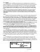
ADJ SND
The ADJ SND terminal is an optionally used input that allows you to have control over the
dimming brightness. By default, the system will turn on the back lights when the DIM terminal
has power, +12V, but this level is adjustable in the Lighting setup menu. Using the ADJ SND
terminal allows you to have a dash mounted control to vary the brightness while the headlights
are on. This requires Dakota Digital’s DIM-1 kit; a stock headlight rheostat will not work.
The DIM-1 has a WHITE/BLUE wire and a BLACK wire. Connect the WHITE/BLUE to the
ADJ SND terminal and the BLACK to ADJ - ground. The dash mounted dimmer will only vary the
display brightness when the DIM terminal has power, +12V.
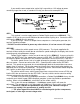
ADJ –
This terminal provides a ground reference for the optionally installed DIM-1 for dash
mounted dimming control. The BLACK wire will connect to the ADJ – terminal, the
WHITE/BLUE connects to the ADJ SND.
*This terminal should not be used for grounding any other sensors or devices as damage
to the control box will occur. If not using a Dakota Digital DIM-1, this terminal should be
left open.