
User manual

Danfoss can accept no responsibility for possible errors in catalogues, brochures and other printed material. Danfoss reserves the right to alter its products without notice. This also applies to products already on order provided that such alterations
can be made without subsequential changes being necessary in specications already agreed. All trademarks in this material are property of the respective companies. Danfoss and the Danfoss logotype are trademarks of Danfoss A/S. All rights
reserved.
Danfoss A/S
Haarupvaenget 11
DK-8600 Silkeborg
Denmark
homeretail.danfoss.com
Fitting the radiator thermostat (TRV)
Danfoss Heating Segment VI JPM102 06/2015
1
4
5
2
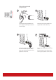
Whilst holding the sensor rmly on the
valve secure connection by turning the
union nut clock-wise by hand. Whilst still
holding the sensor rmly on the valve fully
tighten the metal union.
5
4
3 4
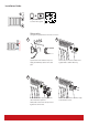
Remove cap from valve and turn sensor to
5. Make sure union nut is turned loosely
up towards the sensor body until it is only
slightly free of the lower part of the sensor
body.
Press the sensor rmly onto the valve, en-
suring that the scale pointer is at top.
Set desired room temperature.
Removing the Sensor:
Turn the sensor to max. position 5. Turn
union nut anti-clockwise to release locking
mechanism.
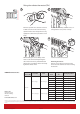
C
Radiator
Sensor (TRV)
Lock Shield Valve
Product
Code
Pipe
size
Building Regulation
RTW- RA
RLV-S Angle RA-FN Angle
013G6506 3/8” (DN 10) DE Building Regulation
013G5607 3/8” (DN 10) FR Building Regulation
013G6508 1/2” (DN 15) DE Building Regulation
013G6509 1/2” (DN 15) FR Building Regulation
013G6514 3/8” (DN 10) SE Building Regulation
013G6515 1/2” (DN 15) SE Building Regulation
RLV-S Straight RA-FN Straight
013G6510 3/8” (DN 10) DE Building Regulation
013 G 6511 3/8” (DN 10) FR Building Regulation
013G6512 1/2” (DN 15) DE Building Regulation
013G6513 1/2” (DN 15) FR Building Regulation
013G6516 3/8” (DN 10) SE Building Regulation
013G6517 1/2” (DN 15) SE Building Regulation
HOME thermostat sets: