
Product Overview


© Danfoss | DCS (jmn) | 2016.11
2 | 520H11543 | DKRCC.PI.CD0.F4.22
Recommendations for capillary tube and are connections:
1. Ensure self-draining of the capillary tube to minimize
clogging.
2. Coil excess capillary tube into smooth, circular coils (approx.
3 inch diameter). The coiled tube should be securely fastened
in order to prevent possible damage due to vibration.
3. Leave a little slack in the capillary tube as it helps to damp
mechanical vibrations.
4. Avoid sharp bends as well as re-bending of the capillary tube
on the same point as it weakens the material, increasing the
risk of crack.
5. Never allow for contact between the capillary tube and sharp
or abrasive objects as during vibrations the tube could be
damaged due to friction.
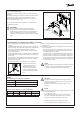
6. Purge the piping before connecting pressure switches.
7. Always use two wrenches
tightening the are nut on
the pressure switch. One
wrench should support the
connector while the second
wrench isused to tighten the
nut.
8. Do not over tighten are nuts as it may damage the threads
causing leaks.
9. Protect the capillary tube from damage caused by vibrations
from compressor:
–
when the switch unit is mounted directly on the compressor,
the capillary must be secured to the compressor so that
everything vibrates as a whole.
– when the switch is mounted remote from the compressor,
make the pressure connections away from thecompressor.
– when the switch is mounted remote from the compressor
and the pressure connections have to be on the compressor,
then damping coils must be used between the compressor
and the pressure switch.
NOTE:
After installing the pressure switch, evacuate theplant in
accordance with applicable EPA and other regulations,
to remove air, moisture, and other contaminants.
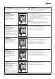
Screws for
bracket mounting
Mounting holes
for at surfaces
120 V AC 24 FLA, 144 LRA – make only
240 V AC 24 FLA, 144 LRA – make only
240 V DC 12 W pilot duty
Wiring
Electrical ratings according to UL regulations
European electrical ratings according to EN 60947
AC1 AC3 AC15 LR DC13
16 A 16 A 10 A 112 A 12 W
400 V 220 V
CAUTION:
Disconnect power supply before wiring connections
are made or service to avoid possible electrical shock or
damage to equipment.
Do never touch live parts with your ngers or with
anytool.
NOTE:
All wiring should conform to the National Electrical Code
and local regulations.
Use copper wire only.
Use terminal screws furnished in the contact block.
Do not exceed tightening torque 20 lb. in (2.3 Nm).
Do not exceed electrical ratings for the switch.
The terminal block as well as grounding screw
are accessible after dismounting of the front cover.
Mount the KPU pressure switch on a bracket
or on a completely at surface.
Mounting to an uneven surface might cause improper switch
operation.
For bracket mounting use only the 10-32x3/16 screws provided
with the switch. If other screws are used function of the
pressure switch might be disturbed (they may not protrude
into the switch more than
1
/
8
in.).
Use only the mounting holes provided; no other holes are to
be added to the switch.
IMPORTANT:
Pressure pulsations in the refrigeration system
reduce life time of the bellows and might disturb
switch function. Pressure pulsations should always be
eectively damped e.g. by connection the pressure
switches to the refrigeration system through a capillary
tube.