
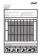
User Guide
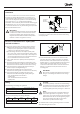

Screws for
bracket
mounting
Mounting holes
for at surfaces
2 DKRCC.PI.CD0.A3.22 / 520H8467 © Danfoss A/S (AC-MC / jmn), 2014-02
Installation
Select an accessible location, where the thermostat will not
be subject to damage. Mount the KPU on a bracket or on a
completely at surface. Mounting on an uneven surface may
cause incorrect thermostat operation. For bracket mounting,
use only the 10-32 x
3
/
16
in. screws furnished with the
thermostat. Other screws may interfere with the functioning of
the thermostat. In no case can screws protrude more than
1
/
8
in. into the thermostat. Use only the mounting holes provided.
Do not make additional holes.
IMPORTANT:
For vapor charged thermostats, ensure that the bulb
is installed in a colder location than the thermostat
housing and capillary tube. This prevents charge
migration from the bulb and ambient temperature
will have no eect on regulation accuracy.
For adsorption charged thermostats, the bulb can be placed
in a warmer or colder location than the thermostat housing
and capillary tube.
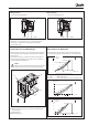
General recommendations for capillary tube
and bulb installation:
1. Protect the capillary tube from damage due to vibration.
a) When the thermostat unit is mounted directly on the
compressor, the capillary tube must be secured to the
compressor so that both vibrate together.
b) For mounting otherwise, form surplus capillary tube
into a loose loop, and secure the length of capillary tube
between the compressor and the loop to the compressor.
Secure the length from the loop to the thermostat to the
base on which the thermostat is mounted.
2. Leave a little slack in the capillary tube to help dampen
vibration.
3. Avoid sharp bends and bending the capillary tube at the
same point several times, as these actions can weaken the
material and increase the likelihood of the tube cracking.
4. Form and locate the capillary tube away from sharp or
abrasive objects that might damage it.
5.
Never allow the capillary tube of a vapor charged
thermostat to run alongside of a suction line in a wall entry.
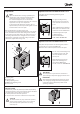
6. Ensure minimal length of capillary tube exposed to
temperature for KPU with straight capillary bulb type:
− 16 in. for KPU tharmostats with 80 in.
capillary tube,
− 22 in. for KPU thermostats with 200 in.
capillary tube.
7. For thermostats with room sensor coils, make sure that
placement allows free airow around the coil and bulb.
At the same time, ensure that the bulb is not exposed to
drafts from doors, or to heat radiated from the evaporator
surface. Make sure that the bulb does not come into
contact with a wall surface. Never mount the thermostat
directly on a cold wall. Instead, mount the unit on an
insulating plate.
IMPORTANT:
Do not dent or deform the bulb of the thermostat, as
doing so could damage the bulb and cause charge
leakage.
Wiring
Electrical ratings according to UL regulations
120 V a.c. 24 FLA, 144 LRA - make only
240 V a.c. 24 FLA, 144 LRA - make only
240 V d.c. 12 W pilot duty
European electrical ratings according to EN 60947
AC1 AC3 AC15 LR DC13
16 A 16 A 10 A 112 A 12 W
400 V 220 V
CAUTION:
To avoid the possibility of electric shock and damage
to equipment, diconnect the power supply before any
wiring connections are made. Never touch current
conducting (LIVE) parts with your ngers or with tools.
NOTE:
All wiring should conform to the National Electrical
Code and to applicable local regulations. Use only
copper wire. Use only the terminal screws furnished in
the terminal block. Do not exceed tightening torque
of 20 inch pounds (2.3 Nm). Do not exceed the
thermostat’s specied electrical ratings.
The terminal block as well as grounding screw are accessible
after dismounting the front cover.