
User Guide
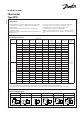

LOAD
~ LINE
LOAD ~ LINE
A
© Danfoss A/S (AC-MC / jmn), 2014-02 DKRCC.PI.CD0.A3.22 / 520H8467 3
Wire dimensions: 10 AWG max.
Cable entry:
7
/
8
in. cable entry for
1
/
2
in. male pipe thread
connection (conduit boss) or similar (Pg 13.5 or Pg 16 )
screwed cable entry.
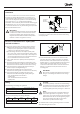
Contact function test (Manual trip)
When the electrical leads are connected the contact function
can be manually tested regardless of temperature conditions
in the system.
The manual trip lever is located in the left side of the KPU. It
must be operated with ngers only. Do not use screwdriver
as it will damage the thermostat.
NOTE:
While operating the manual trip on KPU switches with
manual reset it is necessary to push the reset knob.
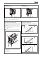
A: Manual trip. Push the lever. Use ngers only!
B: Manual reset button (only on versions sold with manual
reset function)
C: Terminal block
D: Grounding screw
Wiring Option A:
– Cut-Out on temperature fall
Wiring Option B:
– Cut-Out on temperature rise
°C °F
KPU 61
KPU 62
°C
°F
LSP
B
C
°F
D
°C
KPU 63
LSP
°C
°F
LSP
KPU 68
KPU 69
°C °F
°C °F
15
10
0
10
20
30
70
15 ° F
Dierential lines
Dierential lines
130
0 20 40 60 80 100 120
90 80 70 60 50 40 30 20 15
110 90 70 50 30 10 10
55 50 40 30 20 10 0 10 20
50 30 10 10 30 50 70
10
20
30
40
50
35
25
15
5
0
5
60
40
20
0
20
20
0
20
40
60
100
80
60
40
20
20
25 20 10 0 10 20 30 40 50
20 °F
30 °F
20 °F
15 ° F
5 °F
20 °F
10 °F
10 °F
5 °F
Dierential lines
HSP
HSP
HSP
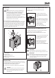
Determination of dierential
For KPU thermostats with vapor charge and automatic reset,
use the following graphs to determine the correct dierential.
Example:
HSP = 45 °F DIFF (from graph):
LSP = 32 °F => 13 °F (value which has to be set on di. scale)