
Install Instructions


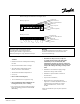
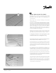

Connection 120V
Phase - Black (L)
Neutral - Blue (N)
Ground - Bare
Danfoss LX Floor Heating System
CAUTION!
It is important that this equipment is installed only by qualified electricians who are familiar with the proper sizing,
installation, construction and operation of floor warming system and the hazards involved. The heating cable is
designed for under floor heating purposes only.
The installation shall be in accordance with the manufacturer’s instructions and national and local codes.
The installation shall be in accordance with Part 424-J, American National Standard Institute / National Fire
Protection Association (ANSI/NFPA70), National Electrical Code (NEC) and Canadian Electrical Code (CEC),
Part 1. Danfoss recommends GFCI for heating cable in normally wet areas (i.e. bathrooms, showers, kitchens).
Connection 240V
Phase - Black (L1)
Phase - Blue (L2)
Ground - Bare
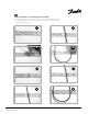
WARNING:
Remember to measure resistance.
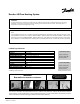
LX Cable Specifications
2
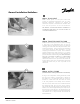
The resistance should be measured between the two conductors, blue and black. Compare the measured resistance
to the resistance on the product label, located 3 inches from the splice, on the cold lead. Also, measure the resistance
between the blue, black and shielding/ground wire. Both should read infinity.
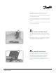
MONITOR YOUR INSTALLATION!
USE THE LITTLE BUZZER CONTINUITY
ALARM (PART#088L0028)
Little Buzzer
Note!
Type:
Voltage:
Output:
Heating Element Size:
Cold Lead
Bending radius:
Cable Diameter:
Wire insulation:
Casing:
Max. Allowable Temp.:
Min. Installation Temp.:
Twin conductor
120V, 240V
3W/ft (10 W/m)
40’ (12.2 m) to 630’ (192 m)
10’ (3.0 m)
Minimum 3/4” (19 mm)
1/8” (3.2 mm)
TM
FEP, Teflon
PVC
212°F (100°C)
50°F (10°C)
Note: Operating the 240V cable at 208V reduces the power output to approximately
2.25W/sq.ft. (25% reduction)
088L3390 - 06/2009