Installation & Operation Manual Danfoss RX Roof & Gutter De-Icing Kit DanfossRX BRINGING WARMTH TO LIFE
Table of Contents Page Welcome/Kit Contents ............................................................................................... 2 Specifications ................................................................................................................ 3 General Information and Planning/Sizing........................................................... 4 Installation Instructions ............................................................................................
Danfoss RX Roof and Gutter De-Icing Cables Thank you for choosing the Danfoss RX Roof and Gutter De-Icing Kit as the solution to your roof snow and ice problems. Danfoss is the world leader in electric radiant heating and the RX product has been designed to produce an effective and constant solution to protect your roof from ice dams and the related hazards. The quality engineered RX heating cables provide a safe, flexible and economical solution to your snow and ice protection requirements.
RX Cable Specifications fect combination for control of cooling and The RA-C valve is a normally open valve. In valve opens when the room temperature is an application with self-acting sensors type rising above the set temperature. heating circuits. FEK or FED it is ensured that the cooling fect combination for control of cooling and Cable Construction: Rated Voltage: Output: Heating Element Size: Bending Radius: Cable Diameter: Power Lead length: Wire insulation: Outer Insulation: Max.
General Information and Planning The Purpose of Danfoss RX Heating Cables: The RX de-icing cable is designed to prevent ice dams from forming on roofs and in gutters and downspouts. When used and installed according to this manual, the RX system provides a path for melted snow and ice to drain from the roof. The Danfoss RX system is not designed to remove ice dams that have already formed, nor should it be used for clearing the entire roof of snow.
Cable Installation It is important to plan the cable layout before any installation begins. Making a drawing of the roof and then chalking the cable locations on the roof surface may be helpful. Remember to always exercise caution when on a ladder or roof. See Appendix A to determine cable lengths required. 1. Choose your start point: To protect the cable from damage and to ensure personal safety, do not start the cable layout close to doorways, entrance areas or sidewalks etc.
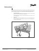
Roofline Pattern: A triangular pattern is used on the edge of the roof (Figure 2). The height of each triangle is dependant on the size of the roof overhang. Refer to Table 3 for triangle heights. Triangle Height 15” Triangle Base Figure 2. Roofline Pattern Table 3 - Triangle Heights Overhang “O” <12” (30.5cm) 12-18” (30.5cm - 45.7cm) 18-24” (45.7cm- 61cm) 24-30” (61cm- 76.2cm) 30-36” (76.2cm- 91.4cm) 36-42” (91.4cm-106.7cm) 42-48” (106.7cm-121.9cm) 48-54” (121.9cm-137.2cm) 54-60” (137.2cm-152.
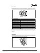
Dormer Pattern: Place the RX heating cable around the perimeter of the dormer, as in Figure 4. Figure 4. Dormer Pattern Valley Pattern Route the cable a minimum of 3' up and down the valley; lengthen as appropriate for a higher roof (Figure 5). Figure 5. Valley Pattern Other areas: Other areas of the roof not mentioned here may also be heated using the triangle pattern to prevent the formation of ice dams.
Double runs of RX cables may be used when ice problems are only present in the gutters (Figure 7). CAUTION: Install such that the heating cable does not touch, overlap or cross itself. Figure 7. Double Cable Run in gutter and downspouts Note: One should take into account the number of cables used when designing the layout. It may be simpler to install the heating system using more short kits, or fewer large kits. Also consider what to do with cable excess or shortage.
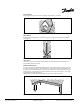
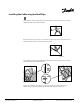
Installing the Cable using the Roof Clips Top of Triangles: lift the shingle gently using the putty knife. Insert the clip and press the shingle down firmly; it will reseal itself in hot weather. Figure 10. Bottom of triangles along roof edge: Create a drip loop over the edge of the roof, leaving at least 2” between the bottom of the drop loop and the gutter bottom. Figure 11. drip loop Top of Triangles: lift the shingle gently using the putty knife.
Use and Maintenance Each snow season: Check cable position Ensure all debris is removed Inspect cable for damage, deterioration Test GFI devices When to operate the heating system: Operate the RX system in the winter season when temperatures fall between 15°F to 35°F (-9°C to 2°C). In very cold temperatures, the RX system may not generate enough heat to prevent the formation of ice dams. Turn off the system when ice dams have melted or temperatures are greater than 35°F (2°C).
RX Kits - 120V Part Numbers Part No. 088L3500 088L3502 088L3503 088L3504 088L3505 088L3508 088L3510 088L3511 Length (feet) 30 65 80 100 120 170 230 265 Watts Amps Ohms 170 310 390 450 535 760 1080 1220 1.4 2.6 3.3 3.8 4.5 6.3 9.0 10.2 85.7 46.2 36.4 26.7 23.1 19.0 13.3 11.8 No. Shingle Clips / Kit 25 25 50 50 75 100 100 125 Each kit comes with 10 spacer clips as standard. Appendix A Find the Required Cable Length Table 1 - Summary of Cable Lengths Item Required Cable Length (ft) Roof Edge (Fig.