
Install Instructions
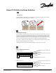

Connection 240V
Phase - Black
Phase - White
Ground - Green
3
Products
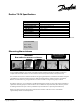
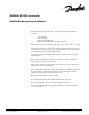
Danfoss TX-FH Specifications
Note : TX-FH cables operated on a 208V power supply will experience a 25% power reduction.
WARNING:
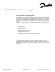
Remember to measure resistance.
Using a digital Ohmmeter, t black and white .
powe
Also, measure the resistance between the black and green (ground) wires, and between the white and green
(ground) wires to test the insulation resistance. Both should should have infinite resistance.
a megaohmmeter 2500
he resistance should be measured between the conductors
Compare the measured resistance to the resistance listed on the product label (on the r lead).
If available,
Danfoss recommends using for this test with a voltage setting of up to V.
Record the resistance on your warranty card. Documenting the resistance at each stage of the installation is
required for warranty purposes. If the resistances do not match the expected values, the cable may need to
be damaged and need repair. Contact your Danfoss representative for a repair kit (part # 088L0010)
While not required, you may also want to measure the resistance of the floor sensor. It should be
approximately 12kΩ at room temperature.
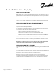
MONITOR YOUR INSTALLATION!
USE THE LITTLE BUZZER CONTINUITY
ALARM (PART#088L0028)
Little Buzzer
Measuring the resistance
Type:
Voltage:
Output:
Heating Element Size:
Power Lead
Cable Diameter:
Wire insulation:
Outer insulation:
Max. Allowable Temp.:
Min. Installation Temp.:
Twin conductor
240V
6 W/ft (20 W/m)
60 ft (18 m) to 680 ft (207 m)
10 ft (3.0 m)
1/4 in ( 6 mm )
TM
FEP, Teflon
PVC
220°F (105°C)
40°F (5°C)
Copyright 2009 Danfoss Inc.
TEL: 866-676-8062. FAX: 905-285-2055
NA.EFHTH-FHM- 07/2009