
Install Instructions


7
STEP 1: PLAN YOUR LAYOUT
Make a sketch of the area to be covered with heating TX-FH cables. Accurately measure the net
area of the floor. This is the area you would walk upon. Do not install heating cable under the
permanent fixtures. Select the cable spacing. Never space cables closer than 4” apart . Danfoss
recommends 6” standard spacing.
You should also plan the location of the thermostats, floor sensors locations and their conduit’s
location. The start of cables should be as close as possible to the thermostat’s final placement.
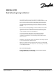
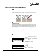
STEP 2: INSTALLING THE FLOOR SENSOR AND CONDUIT
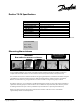
STEP 3: MEASURE THE RESISTANCE OF THE HEATING CABLE
Using a digital ohm-meter, measure the resistance of the TX-FH cable. Compare the measured
value with the resistance listed on the label of the power lead.
Remember to record the measured resistances on the warranty card. Documenting the
resistance at each stage of the installation is required for warranty purposes.
STEP 4: INSTALLING THE TX-FH CABLE
Install the heating cable. You may need to install the cable strapping before installing the TX-FH
cable.
The power lead splice and and at least 12in (30 cm) of the power lead must be embedded in the
mass material. The remainder of the power lead should be in a conduit that extends to the
thermostat or contactor. The power lead may be extended if required.
Measure the resistance once again and record the information on the warranty card.
TIP: Danfoss recommends taking a picture of the cable layout and conduit placement during
installation. This can help in the unlikely case that the cables need repairs and for warranty
claims.
A floor sensor should be installed in a rigid conduit. The conduit protects sensor and facilitates
its replacement in the unlikely event of failure.
The sensor and the conduit may be installed in connection with the actual construction work
and connected at a later date. Please observe the following:
1. Ensure that the conduit is sealed before the concrete is poured.
2. The conduit must be positioned between the heating cables.
3. Place the sensor inside the tube until it reach
4. The floor sensor should be installed at least 10 to 15 in into the heated area.
5. The floor sensor has a standard 10ft (3m) lead that may be extended with 20 AWG wire.
es the end of the conduit.
Danfoss TX-FH Installation - Step by Step
Copyright 2009 Danfoss Inc.
TEL: 866-676-8062. FAX: 905-285-2055
NA.EFHTH-FHM- 07/2009