
Operating Instructions and Installation Instructions
5
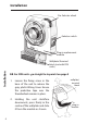
3. Fix the Wallplate/Terminal Block to the wall with
countersunk No.8 woodscrews or to a steel box to BS 4662.
1970 or a surface mounting steel or moulded box having
centres of 23/8” (60.3mm).
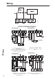
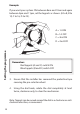
4. Referring to the Wiring Diagrams on page 6, connect the
unit as shown. Ensure that terminals 3 and 6 are linked
where required (Mains Voltage applications) with insulated
cable capable of carrying full load current.
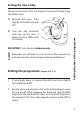
5. Ensure all dust and debris has been cleared away from
the area, then plug the module rmly into the wallplate
ensuring that the hook at the top of the wallplate engages
with the slot at the back of the body. Press the module
down until it locates solidly.
6. Cut a cable aperture in the Wiring Cover if necessary;
replace the Wiring Cover, and tighten the xing screw.
7. Switch on Mains & test for correct operation as follows:
i) Remove protective tape from pre-selector wheel.
ii) Remove dial cover & rotate the clock dial two
complete revolutions to clear the mechanism.
ii) Check that all positions of the Selector Switch
and Tappets operate correctly. (See instructions
in User Booklet.)
8. Replace the dial cover. Finally leave this booklet, containing
the USER instructions with the Householder.
9. If the unit is to be left turned o and is in a dusty
atmosphere, protect the pre-selector wheel by re-a xing
the protective tape.
IMPORTANT: Remove tape prior to putting unit into
service
.
Installation