
Install Instructions

© Danfoss | DCS (CC) | 2016.01AN146886422104en-000501
Danfoss scroll compressors
DCJ / H series
Instructions
1 – Introduction
These instructions pertain to the Danfoss scroll compressors used for HVAC systems. They provide
necessary information regarding safety and proper usage of this product.
2 – Nameplate
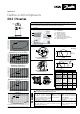
3 - Operating map
70
65
60
SH 11K
55
50
45
40
35
30
25
20
-30 -20 -15-25 -10 -5 50 10 15
Condensing Temperature (°C)
Evaporating Temperature (°C)
70
65
60
SH 5K
SH 11K
HCJ120 & HCJ121
55
50
45
40
35
30
25
20
-30 -20 -15-25 -10 -5 50 10 15
Condensing Temperature (°C)
Evaporating Temperature (°C)
70
65
60
SH 11K
55
50
45
40
35
30
25
20
-30 -20 -15-25 -10 -5 50 10 15
Condensing Temperature (°C)
Evaporating Temperature (°C)
SH 5K
SH 10K
70
65
60
55
50
45
40
35
30
25
20
Condensing Temperature (°C)
-30 -20 -15-25 -10 -5 50 10 15
Evaporating Temperature (°C)
10
15
20
25
30
35
40
45
50
55
60
65
70
-35 -30 -25 -20 -15 -10 -5 0 5 10 15 20 25
Condensing temperature (℃)
Evaporating temperature (℃)
SH5K
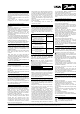
A: Model number
B: Serial Number
C: Manufacturing year
D: Internal protection
E: Supply voltage range
F: Locked rotor current
Maximum operating current
G: Lubricant type and nominal charge
H: Approved Refrigerant
HRM/HLM/HCM-HRP/HLP/HCP Model variation T
(R22/407C)
HRH/HLH/HLJ/HCJ Model variation T (R410A)
HRM/HLM/HCM - HRH/HLH/HLJ/HCJ
Model variation U (R22 / R410A)
HHP (R407C)
DCJ (R410A)
Installation and servicing of the compressor by qualied personnel only. Follow these
instructions and sound refrigeration engineering practice relating to installation,
commissioning, maintenance and service.
The compressor must only be
used for its designed purpose(s)
and within its scope of application
(refer to «operating limits»). Consult
Application guidelines and datasheet
available from cc.danfoss.com
Never operate
compressor without
terminal box cover in
place and secured.
Under all circumstances, the
EN378 (or other applicable local
safety regulation) requirements
must be fullled.
Wear protective goggles and
work gloves.
The compressor is delivered under nitrogen gas pressure
(between 0.3 and 0.4 bar / 4 and 6 psi). Do not disassemble
bolts, plugs, ttings, etc... unless all pressure has been
relieved from the compressor.
The compressor must be handled
with caution in the vertical
position (maximum oset from
the vertical : 15°).
C
S
R
Line
Run
Capacitor
Start
Capacitor
Potential
Relay
1
2
5
C
S
R
Line
Run
Capacitor
Quick connect spade terminals
P terminal box type
push
push
push
A
E
D
C
B
F
G
H
PSC wiring
CSR wiring
4 - Electrical connections
5 - Connections size
C
T₁
Ring connect screw terminals
C terminal box type
S
T₂
R
T₃
Quick connect spade terminals
P & T terminal box type
Single pack
Ring connect screw terminals
C & Q terminal box type
When HRM compressors are used with R417A, the factory
charged oil must be replaced by PVE oil 320HV (120Z5034).
Brazed connection Rotolock connection
Models
Connec.
size
Models
Connec.
size
HRM032-042
HRP034-042
HRM/HRP045-047
HRH029-040
Suction
3/4"
Disch. 1/2"
- -
HRM/HRP048-060
HLM/HLP068-075
HRH041-056
HLH061-068
HLJ061-068
Suction
7/8"
Disch. 1/2"
HRH044-
056
HLH061-
068
HLJ072-083
Suct. 1"1/4
Disch. 1"
HLM/HLP078-081
Suction
7/8"
Disch. 3/4"
- -
HCM/HCP094-120
HCJ090-121
DCJ091-121
Suct. 1"1/8
Disch. 7/8"
- -