
Installation Instructions

1
The Model 841 & 842 Timeswitches must be installed
by a competent electrician and the installation
should conform to IEE Wiring Regulations.
Installation & Wiring
1. Slacken the four fi xing screws, one in each corner of the unit, and
carefully separate the front and rear portions.
CAUTION: Do not allow either half of the unit to hang by the ribbon
cable as damage could be caused.
2. Remove the polystyrene packing piece from the top of the
transformer. It is marked ‘REMOVE’.
3. Select the desired fi xing position and observe the label ‘THIS WAY
UP’ inside the rear portion. The two halves will only assemble
correctly one way round.
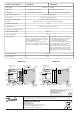
4. Four fi xing holes are provided for attaching the rear portion to the
wall or mounting surface.
Conduit box adaptors as shown below are available if required.
Part No.: 8/3223 Double Gang Surface Box Adaptor
5. Surface cable entries to the units can be made from above, below
or from the left hand side. Conduit or recessed cable entry is
through the aperture in the rear moulding.
6. For surface cable entry remove the appropriate knock-out and
ensure one of the two cable clamps is positioned correctly.
7. Connections to the units should be made as shown below.
MODEL 841
MODEL 842
If the control circuit(s) are to operate at 230V then terminals L
& 1 (Model 841) and terminals L, 1 and 4 (Model 842) must be
linked, ensuring that the cable is sheathed and of a size to carry
the required load current.
If, however, the control circuit(s) are operating at other than 230V
then no link(s) shall be fi tted and in the case of Model 841 both
terminals 1 and 2 should be connected to the load.
841 & 842
Seven Day Pulsed Output Electronic Timeswitches
INSTALLATION INSTRUCTIONS
In the case of Model 842 terminals 1, 2 and 3 (if required) should
be connected to the load controlled by Channel 1 and terminals
4, 5 and 6 (if required) to the load controlled by Channel 2.
8. The unit is supplied set for a 5 second single pulse output. If a multi
pulse output is required, proceed as described in paragraph 10 (b).
If a number of pulses or the pulse duration is required to be different
from supplied, proceed as described in paragraph 11(b).
9. Upon completion of wiring plug in the ribbon cable ensuring the
polarised plug is fully inserted into the socket. Refi t the front half
of the timeswitch ensuring correct alignment and that no cables
are trapped before re-tightening the screws.
10. TO CHANGE FROM SINGLE TO MULTI PULSE OUTPUT
(a) Remove the front portion of the unit as described in ‘Installation
and Wiring’ paragraph 1.
(b) A 2 position slide switch is provided on the rear of the printed
circuit board inside the front portion of the unit.
With the switch positioned OUT (as supplied) this provides a single
pulse output. Slide the switch IN to achieve a multi pulse output
(½ second on followed by ½ second off).
On Model 842 a 2 position slide switch is provided for each channel
to enable different types of pulsed output if required. The switch
relating to each channel is clearly marked.
11. RESETTING OF SWITCHING DURATION
(a) Remove the front portion of the unit as described in ‘Installation
and Wiring’ paragraph 1.
(b) The bank of four miniature rocker switches is mounted on the
printed circuit board inside the front portion of the unit.
When switch no. 1 is ‘on’ 1 second duration is set.
When switch no. 2 is ‘on’ 2 seconds duration is set.
When switch no. 3 is ‘on’ 4 seconds duration is set.
When switch no. 4 is ‘on’ 8 seconds duration is set.
When all 4 switches are ‘on’ the duration is
1 + 2 + 4 + 8 = 15 seconds.
Any combination of the 4 switches may be selected to set from 1
to 15 seconds in increments of 1 second.
If all 4 switches were ‘off’ there would be no output and so this
setting should be avoided.
(c) On Model 842, a bank of four miniature switches is provided
for each channel to enable different switching durations.
EXAMPLES
Cable
Entry
Aperture
2 fi xings for
double gang
surface box
Alternative 4 fi xings
for double gang
surface box
4 fi xings
for Mark 8
Timeswitch
Spare N L 1 2
230V, 50 Hz
Mains Supply
Link for 230V
control circuit
Output
(LOAD)
N L 6 5 4 3 2 1
230V, 50 Hz
Mains Supply
Link for
230V
control
circuit(s)
OFF ON
Channel 2
OFF ON
Channel 1
Slider Switch Posi-
tions
‘ON’
Duration
Slider Switch Posi-
tions
‘ON’
Duration
ON
OFF
1
23
4
ON
OFF
1
23
4
ON
OFF
1
23
4
ON
OFF
1
23
4
ON
OFF
1
23
4
ON
OFF
1
23
4
ON
OFF
1
23
4
ON
OFF
1
23
4
ON
OFF
1
23
4
ON
OFF
1
23
4
ON
OFF
1
23
4
ON
OFF
1
23
4
ON
OFF
1
23
4
ON
OFF
1
23
4
ON
OFF
1
23
4
ON
OFF
1
23
4
NONE
Do Not Use
1 second
2 seconds
3 seconds
4 seconds
5 seconds
(As supplied)
6 seconds
7 seconds
8 seconds
9 seconds
10 seconds
11 seconds
12 seconds
13 seconds
14 seconds
15 seconds