
Manual


55
Installation Guide AMV 410, AMV 413
Danfoss Heating VI.AA.U4.7S DEN-SMT/SI
ENGLISH
Safety Notes
Prior to assembly and commissioning
to avoid injury of persons and damages
of the devices, it is absolutely necessary
to carefully read and observe these
instructions.
Necessary assembly, start-up, and
maintenance work must be performed
only by qualified, trained and authorized
personnel.
Prior to assembly and maintenance work
on the controller, the system must be:
- depressurized,
- cooled down,
- emptied and
- cleaned.
Please comply with the instructions of the
system manufacturer or system operator.
Definition of Application
The electrical actuator is used in
connection with the following valves:
VFG 2(21), VFG 25, VFU 2, VFGS 2, AFQM
and AFQM 6.
Fields of application are the temperature
control of water, water-glycol mixtures
and steam for heating, district heating and
cooling systems.
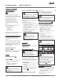
Safety Return Function and
Effective Direction
2
Safety function and effective direction of
stem: valid only for AMV 413.
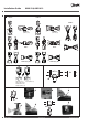
Mounting
Permissible Installation Positions
1
Valve Installation
3
1. Install strainer in front of valve.
2. Rinse system before installing valve.
3. Observe flow direction on the valve
body.
Flanges in the pipeline system must be
in parallel direction, the sealing surfaces
must be clean and undamaged.
4. Install valve.
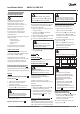
Actuator and Valve Installation
4
The actuator must only be mounted with
the stem retracted
.
Stroke indicator
must be in position .
On delivery the stem is retracted with a
screwed-in mounting screw .
If this is not the case, then:
1. Carry out the electrical connection, see
next section.
2. Press push-button and completely
retract the stem .
3. Screw in mounting screw up to its
stop.
4. Place actuator on the valve and align.
5. Tighten union nut torque 100 Nm.
6.
It is absolutely necessary to unscrew
the mounting screw
, otherwise, the
actuator is out of function.
7.
If the actuator is installed in a downward
hanging position , remove label .
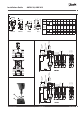
Insulation
5
Dimensions
6
Flanges: connection dimensions acc. to
EN 1092-2, seal form C.
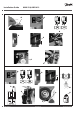
Electrical Connection
7
HIGH VOLTAGE !
Danger of injury and life in case of
improper handling.
Switch off power supply prior to
connecting lines.
The electrical connection must only be
performed by an expert electrician.
Procedure
1.
Unscrew cap nut and remove cover .
2. Connect lines in accordance with
connection diagram.
3. Prior to remounting the cover, carry out
settings at the actuator, see part
8
.
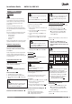
Electrical Connection Diagram
8
Connection for:
STB - Safety Temperature Limiter
STW - Safety Temperature Monitor
SDB - Safety Pressure Limiter
Prior to connection, it is absolutely necessary
to remove the jumper (terminals 4-7).
Only types AMV 413 with safety return
function.
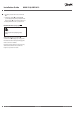
Mechanical Stroke Setting
9
The stroke of the electrical actuator must
be adjusted to the valve stroke.
1. Unscrew the mounting screw .
2. Press push-button until the valve
is completely closed (VFU 2
completely
open) and the direction
indicator stops.
Observe stroke indicator, it must move to
position .
3. Turn the screw until the cam
with line of the selected stroke is
aligned with the actuator of the end
switch.
Note:
Select the valve stroke from the table below.
Type DN 15 20 25 32 40 50 65 80
VFG 2
VFG 21
VFG 25
mm
6 8 12 18
AFQM - 12 18
AFQM 6 - 8 12 -
VFU 2 8 10 14 20
Note:
Only special actuator types are equipped
with end switches, see rating plate.
The adjustment of the end switches must
be done after the stroke has been set.
a. Unscrew the »Allen key« screw
b. Adjust the stroke of the electrical
actuator regarding to chapter:
”Mechanical stroke setting”
Adjusting the Additional
End Switch
10
1. Press push-button until the valve
is completely closed (VFU 2
completely open) and the direction
indicator stops.
Observe stroke indicator, it must move to
position .
9