MAKING MODERN LIVING POSSIBLE Commissioning DHP-AQ www.heating.danfoss.
Danfoss A/S is not liable or bound by warranty if these instructions are not adhered to during installation or service. The English language is used for the original instructions. Other languages are a translation of the original instructions.
Commissioning Table of Contents 1 About documents and decals . . . . . . . . . . . . . . . . . . . . . . . . . . . . . . . . . . . . . . . . . . . . . . . . . . . . . . . . 1.1 Symbols in documents . . . . . . . . . . . . . . . . . . . . . . . . . . . . . . . . . . . . . . . . . . . . . . . . . . . . . . . . . . 1.2 Symbols on decals . . . . . . . . . . . . . . . . . . . . . . . . . . . . . . . . . . . . . . . . . . . . . . . . . . . . . . . . . . . .
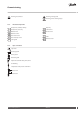
Commissioning 1 About documents and decals The following documents are available for this product: ! The Wiring diagrams that contain the wiring diagram for the heat pump intended for fault tracing and service. The Wiring diagrams are available for download as below. ! The User manual must handed over and gone through with the end customer. Supplied with the heat pump on delivery. ! Country specific instructions and forms are available where relevant. Supplied with the heat pump on delivery.
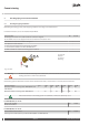
Commissioning Warning, hot surfaces! Warning, moving parts! Warning, risk of crushing injury! 1.2.2 Electrical components Component, ordinary delivery Component, accessory 3 50 54 55 71 1.2.
Commissioning 2 Checking piping and electrical installation 2.1 Checking the piping installation Before filling the heating system, check the piping installation according to the checklist below. For further information, also see the Installation Quick Guide. Piping checklist Are the pipe connections in accordance with the connection diagram.
Commissioning 2.2 Checking the electrical installation Before turning on electrical power, check the electrical installation according to the checklist below Electrical installation checklist Are circuit-breakers installed? One for indoor unit and one for outdoor unit (not included in the delivery) Are correct fuses installed? See fuse table below Positioning of the outdoor sensor.
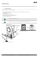
Commissioning 3 Filling and bleeding See Installation Quick Guide for more information. 1. 2. 3. 4. 5. 6. 7. Fill the system with cold water by opening the filler valve, that is on the valve pipe, to a pressure of 1 bar. Open all radiator valves fully. Bleed all radiators. Bleed the outdoor unit. See figure 3. Refill the heating system to a pressure of 1 bar. Repeat the procedure until all air has been removed. Check the system for leakage. Leave all radiator valves fully open.
Commissioning 4 Configuration of control system ! ! To avoid alarms during start-up, the outdoor unit must be powered on. Make the settings in the order they appear in the text that follows Further information about parameters in the control system are found in the Information Menu and Service Menu chapters in the Technical Description 4.1 Select display language The following settings are made in the Information Menu. To enter the Information Menu, press left (<) arrow.
Commissioning 4.3 Factory setting This setting is the setting that will be the future default setting. It will not affect the previously made size setting. The following settings are made in the Service Menu. If not already in the Service Menu, enter the Service Menu by pressing and holding left (<) arrow for at least 5 seconds. Use + or – to move up and down in the menu.
Commissioning 4.5 Set hot water start temperature and activate hot water Start by setting the start temperature to 40°C. The start temperature setting is made in the Service Menu. If not already in the Service Menu, enter the Service Menu by pressing and holding left (<) arrow for at least 5 seconds. Use + or – to move up and down in the menu.
Commissioning Caution Power steps 1 2 3 4 5 +4 Check installed fuses before making any settings.
Commissioning 4.7 Activate electrical auxiliary heater in DHP-AQ Mini ! If a single power stage heater is used (on/off heater, can be an oil burner or equivalent), this setting is the appropriate one. The potential free outputs must be used. If a multi power stage heater is installed, use the settings in the chapter above: "Activate the electric auxiliary heater in DHP-AQ Midi and DHP-AQ Maxi" The following settings are made in the Service Menu.
Commissioning Parameter COOL.HYST.RS LOW COOL.HYST.RS HIGH Meaning This setting is available only if ROOM SENSOR is activated The compressor is stopped if the temperature from the room sensors drops below the desired temperature minus the value set in COOL.HYST.RS LOW Default setting: +1°C This setting is available only if ROOM SENSOR is activated The compressor is started when the temperature rises above the desired temperature plus the value set in COOL.HYST.RS HIGH . Default setting: +1°C 4.
Commissioning 5 5.1 Manual test Caution The installation may only be commissioned if the heating system and water heater have been filled and bled. Otherwise the circulation pump can be damaged. Caution Any alarms that may occur in connection with the installation must be fault-traced. Activate MANUAL TEST Two persons is recommended when doing the manual tests. One at the control display and one at the outdoor unit.
Commissioning Parameter COMPR.HE Meaning 0 = compressor heater off 1 = compressor heater on DRIP TRAY 0 = drip tray heater off 1 = drip tray heater on REV.V. HOT WATER 0 = reversing valve in heating mode 1 = reversing valve in hot water mode IMM. HEAT 1 0 = stop of internal immersion heater power stage 1 1 = start of internal immersion heater power stage 1 IMM. HEAT 2 0 = stop of internal immersion heater power stage 2 1 = start of internal immersion heater power stage 2 IMM.
Commissioning ! The optimum option must be activated. See "Activation of optimum (variable speed) pump" in the chapter "Configuration of control system" In the MANUAL TEST menu: 1. Use + or – to navigate to the CIRC. PUMP entry ! Press + to set circulation pump speed. Set a value between 30% and 100%. ! Check that the circulation pump is running by listening and/or placing a hand on the circulation pump. 2. Stop the circulation pump by setting the CIRC. PUMP value to 0.
Commissioning 5.5 Test the auxiliary heater 1. Start the circulation pump by setting the value CIRC.PUMP to: 1 (OPTIMUM not selected), 30-100% (OPTIMUM selected) . 2. Start the auxiliary heater by setting the value of present EXT. AUX. HEAT to 1. 3. Check that the auxiliary heater works by exiting the MANUAL TEST menu and enter the INFORMATION -> OP. DATA menu and check that the temperature of SUPPLY LINE rises. 4. Return to the menu MANUAL TEST and stop the auxiliary heater by setting EXT. AUX.
Commissioning Parameter CURRENT DISCH. PIPE SUCTION GAS EVAP. PRESSURE DEFR SENSOR 5.9 Meaning Displays the current consumption in Amperes. The set value for MAX CURRENT is shown in brackets. Only appears if CURRENT LIMITER is selected in the Service menu. Shows the temperature at the discharge pipe sensor. Shows the temperature of the suction gas. Shows the pressure of the suction gas pipe. Measured in bar atmospheric pressure, bar (a). Shows the temperature of the defrost sensor.
Commissioning 6 Starting up Now it's time to start the system and do the final settings and adjustments. 6.1 Starting the system Set the heat pump to the desired operating mode in the menu INFORMATION -> OPERAT. The following operating modes are available: Parameter (OFF) AUTO COMPRESSOR AUX. HEATER HOT WATER MANUAL TEST ! 6.2 Meaning The installation is fully switched off. This mode is also used to acknowledge certain alarms.
Commissioning Default setting: 7V, range: 3V – 10V (30 - 100%) The following settings are made in the Service Menu. If not already in the Service Menu, enter the Service Menu by pressing and holding left (<) arrow for at least 5 seconds. Use + or – to move up and down in the menu. ! SERVICE ! OPTIMUM ! START FLOW CIRC. ! Press + to set the start circulation pump speed. See note below. ! Press left arrow several times to exit the SERVICE MENU ! Start with a high setting, for example 10V.
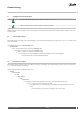
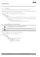
Commissioning 6.3 Reinstall the lower front hatch and side cover atec-040 After completed checks and tests the lower front hatch and side cover must be reinstalled on the out door unit. See figure 5. T25 Fig.
Commissioning 7 Tuning the system 7.1 Tuning the heating system To obtain a heating system balance and obtain an even and comfortable indoor temperature, the heating system may need adjustment according to the example below. The indoor temperature is adjusted by changing the heat curve. The heat curve calculates the supply temperature depending on the outdoor temperature. The lower the outdoor temperature, the higher the supply temperature.
Commissioning - *+ & 1. 2. 3. 4. 5. * )' &) Supply temperature (°C) Maximum supply temperature Outdoor temperature (°C) 0°C Value for CURVE is 40°C , &' ' (& ' ) Fig. 6: Graph showing the set value 40 for CURVE. In the event of outdoor temperatures below 0°C, a higher setpoint value is calculated and in the event of outdoor temperatures greater than 0°C, a lower setpoint value is calculated. - & *+ 1. Supply temperature (°C) 2. Maximum supply temperature 3.
Commissioning - *+ & 1. Supply temperature (°C) 2. Desired supply temperature 3. Outdoor temperature (°C) )' &) , &' ' (& ' Fig. 8: Changing the ROOM value changes the heat curve upwards or downwards The relationship of the supply temperature to the outdoor temperature will not be affected. 7.4 Adjusting the CURVE at -5°C, 0°C and +5°C Sometimes, at outdoor temperatures between -5°C and +5°C, part of the heat curve may need adjusting if the indoor temperature is not constant.
Commissioning 8 Installation protocol and customer info Fill in the Installation protocol in the User Guide. After installation and test operation, the customer must be informed about their new heat pump installation. In the User guide there is a checklist regarding the information that the installer must give the customer. ! 26 The serial number must always be given for warranty matters. The serial number is on the type plate, which is attached to the heat pump and control unit.
Commissioning 9 Important information/Safety regulation 9.1 General safety precautions Warning Risk of personal injury! Children are not permitted to play with the product. Warning As the water temperature in DHP-H Opti Pro and DHP-L Opti Pro becomes extremely hot, a mixer valve must be installed between the cold water and hot water pipes to ensure a lower domestic hot water temperature. Alternatively the maximum hot water temperature must be reduced in the Service menu.
Commissioning 9.1 Caution The hot water tank must be equipped with an approved safety valve. Caution Heating systems with closed expansion tanks must also be supplied with approved pressure gauges and safety valves. Caution Cold and hot water pipes and overflow pipes from safety valves must be made of heat resistant and corrosion-resistant material, for example copper. The safety valve overflow pipes must have an open connection to the drain and visibly flow into this in a frost-free environment.
Commissioning Warning 9.4 Risk of personal injury! Refrigerant exposed to a naked flame creates a poisonous irritating gas. This gas can be detected by its odour even at concentrations below its permitted levels. Evacuate the area until it has been sufficiently ventilated. Work on the refrigerant circuit Caution When repairing the refrigerant circuit, the refrigerant must not be released from the heat pump, it must treated in the appropriate way.
Commissioning 9.3 9.4 30 Water quality Caution A normal heating system always contains a certain amount of corrosion particulates (rust) and sludge products from calcium oxide. This comes from acid that is naturally occurring in the fresh water that the system is filled with. It is not good practice to have to fill the heating system regularly which is why any leakage in the heating system should be repaired immediately. Normal filling should occur only once or twice a year.
Commissioning Danfoss Heating Solutions VIGFH102 31
Commissioning Danfoss Heat Pumps Box 950 671 29 ARVIKA Phone +46 570 81300 E-mail: dhpinfo@danfoss.com Internet: www.heating.danfoss.com Danfoss can accept no responsibility for possible errors in catalogues, brochures and other printed material. Danfoss reserves the right to alter its products without notice. This also applies to products already on order provided that such alterations can be made without subsequential changes being necessary in specifications already agreed.