
User manual


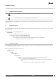

2.2 Checking the electrical installation
Before turning on electrical power, check the electrical installation according to the checklist below
Electrical installation checklist OK Not OK
Are circuit-breakers installed?
One for indoor unit and one for outdoor unit (not included in the delivery)
Are correct fuses installed? See fuse table below
Positioning of the outdoor sensor. See image below
Is communication cable between heat pump and control centre connected? See Installation Quick Guide
Especially check the shield connection
!
Communication cable must be 2 pair shielded Twisted Pair and UV resistant for out-
door use.
Fuse table
Fuse table Unit 6 kW 9 kW 11 kW 13 kW 16 kW 18 kW
230V 1-N 50Hz heat pump A 20 32 —
230V 1-N, 50Hz control unit A
16
17
/30
18
/40
19
400V 3-N 50Hz heat pump A 10 16
400V 3-N, 50Hz control unit A
10
12
/16
13
/16
14
/20
15
/25
16
12) Heat pump with 3 kW additional heater.
13) Heat pump with 6 kW additional heater.
14) Heat pump with 9 kW additional heater.
15) 12 kW additional heater. (Compressor off). Power step 4
16) 15 kW additional heater. (Compressor off). Power step 5
17) Heat pump with 3 kW additional heater.
18) Heat pump with 6 kW additional heater.
19) Heat pump with 9 kW additional heater.
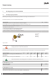
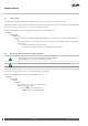
Positioning of the outdoor sensor
H
2/3 x H
Recommended location
Unsuitable location
!
Position the outdoor sensor on the north or north west side of the
house.
!
Make sure that the outdoor sensor is not placed in direct sun light.
!
For higher buildings, the sensor should be positioned between the
second and third storeys. Its location must not be completely pro-
tected from the wind but not in a direct draft. The outdoor sensor
should not be placed on reflective panel walls.
!
The sensor must be positioned at least 1 m from openings in the
walls that emit hot air.
!
If the sensor cable is connected through a pipe, the pipe must be
sealed so that the sensor is not affected by outgoing air.
Commissioning
Danfoss Heating Solutions VIGFH102
7