User manual DHP-AQ VUGFB102
Danfoss A/S reserves the right to make changes to components and specifications without prior notice. © 2010 Danfoss A/S. The Swedish language is used for the original instructions. Other languages are a translation of the original instructions.
Contents 1 Foreword ................................................................................................................................................. 3 2 Safety precautions ................................................................................................................................ 4 3 2.1 Installation and maintenance ............................................................................................................. 4 2.2 System modifications ............
1 Foreword Buying a heat pump from Danfoss is an investment in a better future. A Danfoss heat pump is classed as a renewable energy source, which means that it is considerate of our environment. It is a safe and convenient solution that provides heating, hot water and in certain cases cooling, for your home at a low cost. We thank you for the confidence that you have shown in us by buying a heat pump from Danfoss. We hope that you will benefit from it for many, many years to come.
2 Safety precautions The heat pump cover and control unit cover must only be opened by authorised service technicians. This product is not intended for persons (including children) with reduced physical, sensory or psychological capacity, or who do not have knowledge or experience, unless supervised or they have received instructions on how the apparatus functions from a safety qualified person. Children are not permitted to play with the product.
2.2 System modifications Only authorized installers may carry out modifications on the following components: • • • The heat pump unit Water and electrical installations The safety valve Do not carry out construction installations that may affect the operational safety of the heat pump. 2.3 Safety valve The following safety precautions apply to the hot water circuit’s safety valve with corresponding overflow pipe: • • Never block the connection to the safety valve’s overflow pipe.
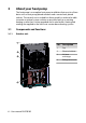
3 About your heat pump The heat pump is a complete heat pump installation that consists of two basic units: a heat pump placed outdoors and a control unit placed indoors. The control unit is available in three models in order to be able to create as optimal system solution as possible, both in an existing heating system that is to be upgraded and in new builds. Heating and cooling are supplied to the house via a water borne heating system. 3.1 Components and functions 3.1.1 Outdoor unit 3 Pos.
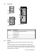
3.1.2 Control unit 5 3 4 1 DHP-AQ Mini 2 1 3 4 2 1 DHP-AQ Maxi DHP-AQ Midi 3.1.3 Position Description 1 Control module (transparent in image) 2 Immersion heater 3 Reversing valve 4 Circulation pump 5 Water heater Heating The heat pump can produce heat for heating (house, pool) and hot water. The hot water requirement is prioritised before the heating requirement. The heating requirement is calculated from outdoor temperature and set heat curve.
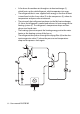
• • • • • A fan draws the outdoor air through an air heat exchanger (1), which heats up the cold refrigerant, which evaporates into a gas. The refrigerant that is now supplied with energy in the form of heat is transferred via the 4 way valve (2) to the compressor (3), where its temperature and pressure are increased. The extremely hot refrigerant continues to the flat heat exchanger (4). Here, the refrigerant is cooled and releases its heat energy to the heating system (5).
3.1.4 Hot water function DHP-AQ Midi and DHP-AQ Maxi are adapted for hot water production. Production of heating and hot water cannot occur at the same time because the reversing valve for heating and hot water is positioned after the heat pump and the immersion heater. Hot water production is prioritised ahead of heat and cooling.
transferring heat to the refrigerant circuit, which is then given off in the air heat exchanger. If the hot water heater is installed the control unit will alternate between cooling and hot water production with prioritisation for the hot water requirement. 3.1.7 Speed controlled fan The fan starts at a nominal speed, which differs depending on the size of output. The fan speed is adjusted up or down as required which is determined by the temperatures in the refrigerant circuit. 3.1.
230V 3.1.10 400V Step 5 15 Step +4 12 Step +5 15 Speed (rpm) control A heat pump requires optimum conditions in the heating system in order to be able to run as efficiently as possible. The temperature difference between the heating system’s supply line and return line must be constant between 7–10°C. If the differences are greater or less, the heat pump is less efficient and savings are lower.
4 Control system The heat pump has an integrated control system which automatically calculates the heating and cooling demand in the house to ensure that the correct amount of heating and cooling is produced and emitted where necessary. The control panel is operated using a keypad and information is shown in a display and by an indicator. The information in the display and menus will vary depending on the menu selection made and connected accessories. ROOM 20°C NO HEAT DEMAND 3 OPERAT. AUTO 1. 2. 3.
• • • 4.3 Not lit, means that the heat pump is not powered. When the green light shines continuously, the heat pump has power and is ready to produce heat, cooling or hot water. Flashing green, means an active alarm. Display The display shows information about the heat pump’s operation, status and any alarms. Table 1. Symbols shown in the display. Symbol F Meaning COMPRESSOR Indicates that the compressor is in operation. LIGHTNING Indicates that the auxiliary heater is in operation.
Symbol Meaning FAN Displayed when the fan is active. COOLING Displayed if cooling is produced. A = Active cooling. The following operating information may also appear: Message Meaning ROOM Shows the set ROOM value. Standard value: 20°C. If the accessory room sensor is installed it shows the actual temperature and the desired indoor temperature is shown within brackets. START Indicates that there is a need for heat production or hot water and that the heat pump will start.
4.4 Main Menu The display's INFORMATION menu is used to set and adjust the heat pump functions and is opened by pressing the left or right buttons. The appearance of the menu will vary depending on the menu selection made and connected accessories. The basic menu appears as follows: 2 3 4 INFORMATION OPERAT. HEATING HOT WATER DEFROST CALENDAR 1 1. 2. 3. 4.
5 Settings and adjustments The installer carries out the basic settings of the heat pump at installation. A number of settings and adjustments that you can carry out yourself are described below. Before changing the control computer’s settings, first find out what these changes mean. Make a note of the default setting. 5.1 Setting operating mode OPERAT. 1. AUTO COMPRESSOR AUX. HEATER HOT WATER MANUAL TEST 2. 3. 4. Open the menu OPERAT. in the INSTALLATION menu.
Operating mode Meaning HOT WATER In this mode the heat pump only produces hot water, no heat goes to the heating system. MANUAL TEST Only displayed when the value for MANUAL TEST is set to 2 in The SERVICE menu. Outputs that control components are activated manually. Caution! If the operating mode OFF or HOT WATER is to be used for long periods during the winter, the water in the heating system in the heating system must be drained, otherwise there is a risk of frost damage.
point that the control regulates against is lowered or raised respectively. When you increase the CURVE value, the heat curve will become steeper and when you reduce it, it will become flatter. This is the most energy and cost efficient way to set the indoor temperature and should therefore be used for long term temperature settings. 1 56 2 5 40 24 1. 2. 3. 4. 5.
Parameter Description HEAT STOP This function stops all production of heat when the outdoor temperature is equal to, or higher than, the set heat stop value. SETBACK TEMP The temperature that will apply at temperature setback controlled from the CALENDAR menu. High temperatures in an underfloor heating system can damage parquet floors. Adjust the heat curve in the HEATING sub-menu as follows: HEATING CURVE MIN MAX CURVE +5 CURVE 0 CURVE -5 HEAT STOP 40˚C 10˚C 55˚C 0˚C 0˚C 0˚C 17˚C 1. 2. 3. 4. 5.
1. 2. 3. 5.3 Press either the + or - button once to open and change the ROOM value. Raise or reduce the ROOM value using the + or - buttons to change the indoor temperature. Wait ten seconds or press the left button once to exit the menu. Distribution circuit 1 and 2 In addition to the main circuit for heating and cooling two distribution circuits can be controlled individually. The same parameters are used for these as in the main circuit (menu HEATING). 5.
5.6 Reading off temperatures OP. DATA OUTDOOR 0˚C ROOM 20˚C SUPPLY LINE 38(40)˚C RETURN LINE 34(55)˚C SYSTEM SUPPLY 35(40)˚C DISTR. CIRC. 1 32(35)˚C DISTR. CIRC. 2 28(30)˚C The set point value for the supply line and the max value of the return line is shown within brackets The max value indicates the temperature at which the compressor is stopped. No values can be changed in this menu. The different temperatures that the installation has are shown here.
1. 2. 3. 4. 5. 6. 7. 5.9 Press either the right or left button once to open the INFORMATION menu. The cursor is in the OPERATION menu option. Press the down button to move the cursor to the DEFROST menu option. Open the menu by pressing the right button once. Press the down button to move the cursor to the MANUAL DEFROST menu option. Press the right button once. Press the up button once to start defrost. Press the left button three times to exit the menu.
5.10 Alarm history NAME ALARM displays information about up to 10 alarms with type of alarm, time and date.
6 Regular checks 6.1 Checking operation During normal operation, the alarm indicator lights green continuously to show that everything is OK. When the alarm is triggered, it flashes green at the same time as a text message is shown in the display. ALARM LOW PRESSURE ERROR Regularly check the alarm indicator to ensure that the installation is working correctly.
Message Meaning ERR PHASE SEQ. Can be displayed in conjunction with interference in the mains network, for example after a temporary power cut. Reset the alarm as follows. If necessary switch off the power supply for a minute or two. Other alarm message Reset the alarm as follows. If the alarm remains contact a service technician. Resetting the alarm For alarms that are not reset automatically acknowledgement is required.
line, its outlet opening facing downwards. If the safety valve is not checked regularly, the water tank might be damaged. It is quite normal that the safety valve lets out small amounts of water when the water tank is being charged, especially if a lot of hot water was used previously. Both safety valves can be checked by turning the cap a quarter of a turn clockwise until the valve lets out some water through the overflow pipe. If a safety valve does not work properly, it must be replaced.
1. 2. 3. 4. 5. 6. 7. 8. 9. 10. Switch off the heat pump. Turn the stopcock to the closed position (see figure above). Unscrew the cover and remove it. Remove the strainer. Rinse the strainer. Reinstall the strainer. Check that the o-ring on the cover is not damaged. Screw the cover back into place. Turn the stopcock to the open position. Start the heat pump.
7 Default setting in the control computer The first column in the table below shows the parameters that can be adjusted by the User. The second column shows settings made at the factory, and the third column the settings made by the installation contractor in connection with installation of the heat pump. Setting Factory setting ROOM 20°C OPERAT.
8 Installation protocol Heat pump model ............................................................... Serial number ............................................................... Type of collector ............................................................... Volume of brine (litres) ............................................................... Pipe installation – Company ............................................................... - Contact person ......................................
9 Check list Positioning □ Surface adjustment □ Drainage Pipe installation, hot and cold side □ Pipe connections in accordance with the diagram □ Flexible hoses □ Expansion and bleed tank □ Strainer, hot and cold side □ Pipe insulation □ Open radiator valves □ Leak test, hot and cold side Electrical Installation □ Circuit-breaker □ Fuse □ Positioning of the outdoor sensor Commissioning □ Bleeding, hot and cold side □ Settings control system □ Manual test components □ Manual test different operating conditi
□ Safety precautions □ Control computer, function □ Settings and adjustments □ Regular checks □ Reference to service requirement □ Warranties and insurances User manual VUGFB102 – 31
10 Service schedule To achieve best performance and service life we recommend Danfoss that the heat pump is serviced at 12 month intervals.
VUGFB102